


Description
RC Switch with Small Low-Side MOSFET - Pololu 2802
This RC switch from Pololu converts hobby radio control pulses to digital on/off signals and has an integrated small, low-side MOSFET that allows it to drive small loads (up to around 3 A), such as lighting or small actuators. The activation threshold and direction are configurable, and a safe-start feature reduces the likelihood of unexpected activation.
The Pololu RC switch with Small Low-Side MOSFET can be used with standard hobby radio control systems for radio control switch applications or simple interface applications. Example uses include converting extra RC receiver or servo controller outputs to simple high/low signals that can control LEDs or relays and connecting RC systems to microcontroller projects that do not have the necessary resources for decoding the RC interface. Two outputs indicate the presence of a valid signal and whether the switch is on or off, and an integrated low-side MOSFET turns on when the switch is on, allowing the board to drive small loads directly. The switch also features a flyback (or freewheeling) diode across the load outputs so that you can connect a coil to them, such as a motor or relay, without any additional external components.
The board requires a 2.5–5.5 V power source supplied to VCC. The board’s MOSFET can deliver up to around 3 A with VCC at 5 V and can handle load supply voltages up to 30 V.
The RC switch measures the width of incoming RC pulses and compares it to a user-configurable threshold (with ±64 µs of hysteresis) to decide whether to turn on the MOSFET. By default, the threshold is approximately 1700 µs, with switch activation occurring above the threshold (longer pulses), but the switch has a learning mode that allows you to change the threshold and the activation direction. A safe-start feature reduces the likelihood of unexpected activation.
RC Switch User Guide
RC Switch Specifications:
- Maximum output current: 3A
- Minimum logic voltage: 2.5V
- Maximum logic voltage: 5.5V
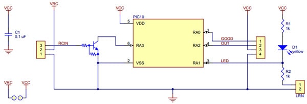
RC Switch Schematic:
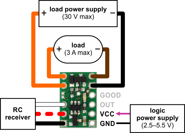
Connecting the RC Switch Typical Connection:
Connecting the RC Switch with Digital Output:
The typical way to connect the Pololu RC Switch with Digital Output is shown in this diagram: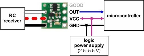
The RC switch can be plugged directly into an RC receiver or servo controller using a Female-Female servo extension cable. These can be found in our Servo Cables category. The switch will read the signal from the RC receiver, but in the default configuration it will not draw or supply any power to the receiver, so the power wire is optional. The receiver will need its own power source.
Power for the switch’s logic needs to be applied to GND and VCC and must be between 2.5 V and 5.5 V. Many microcontroller boards have a 3.3 V or 5 V line that powers the microcontroller and would also be suitable for powering the RC switch.
The OUT pin can be connected to a digital input pin on the microcontroller.
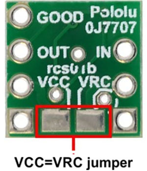
The RC Switch Power jumper:
The setup described above involves two separate power supplies. For some applications, this setup can be simplified by bridging the VCC=VRC power jumper on the bottom of the board. This allows you to either power the microcontroller and RC switch from the RC receiver’s power supply or to power the RC receiver and RC switch from the microcontroller’s power supply.
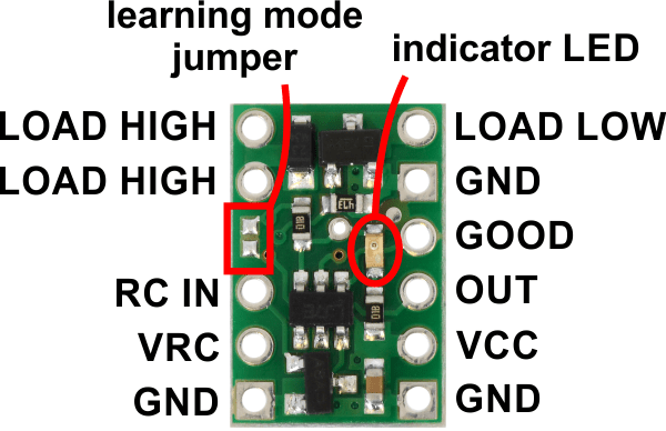
RC Switch Board and Pin Layout:
The RC switch provides feedback about what state it is in via a yellow indicator LED. Status information is also provided on two output pins:
- The GOOD pin indicates the presence of a valid RC signal (10–330 Hz pulse rate, 0.5–2.5 ms pulse width).
- The OUT pin indicates whether the MOSFET is on.
RC interface:
The GND, VRC, and RC IN pins make up the switch’s RC interface and can be connected directly to an RC receiver or servo controller:
- The GND pin is the ground or reference voltage.
- The VRC pin connects to the RC power line. The power from VRC is not used by default, but a jumper on the bottom of the board can be bridged with solder to power the board from VRC as described below.
- The RC IN pin is the RC signal input. The switch measures the width of pulses on this line and uses that to decide whether to activate or not.
Power:
This board involves three potentially-different power supplies:
- VCC: The VCC pin powers the basic functions of the board and needs to be connected to a power source between 2.5 V and 5.5 V. VCC is also the gate voltage that is used to turn the MOSFET on, so it should be noted that lower VCC voltages will lead to higher MOSFET on resistances, which in turn limits the maximum current the device can switch.
- VRC: The VRC pin will generally be connected to the power line from your RC system. By default, power from this pin is not used by the board, so this pin is optional.
- LOAD HIGH: The two pins labeled LOAD HIGH will generally be connected to the positive terminal of the load power supply and to the positive terminal of the load.
Load interface:
The LOAD LOW and LOAD HIGH pins are connections for your load and load supply. The LOAD LOW pins are normally disconnected from GND, but when the switch activates the MOSFET turns on and connects LOAD LOW to GND. There is a flyback (also known as a “freewheeling”) diode between LOAD LOW and LOAD HIGH. The board’s MOSFET can deliver up to 3 A with VCC at 5 V and can handle load supply voltages up to 30 V
Included hardware:
A 12-pin 2.54mm (0.1″) straight breakaway male header is included with the Pololu RC Switch with Small Low-Side MOSFET.
The header pins can be used to connect the RC switch to perf-boards or breadboards.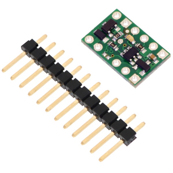
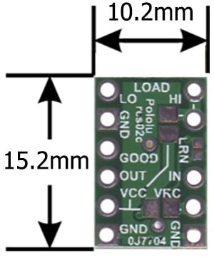
RC Switch Dimensions:
- Board Length: 15.2mm (0.6")
- Board Width: 10.2mm (0.4")
- Weight: 0.5 g (0.02 oz)
RC Switch Documents:
2 Reviews
-
Title of review 53364
This is the switch you need for single-channel escapements. Highly recommended. Phil_G
-
Title of review 893
Replaces the same unit I blew up when I connected the power supply the wrong way round. Works really well. Could do with having slightly less hysteresis but perfectly useable.
Related Products

RC Switch with Medium Low-Side MOSFET
Pololu


MOSFET, P-Channel, 20V, 24A, Low VGS, TO-220
Sparkfun

Power MOSFET STP36NF06 N-Channel 5V Logic Switched
Proto-PIC


RC Switch with Relay Range


MOSFET Power Control Kit
Sparkfun