Sparkfun
16 Output I/O Expander Breakout Board - SX1509

- SKU:
- PPBOB-13601


Description
16 Output I/O Expander Breakout Board - SX1509 - SparkFun BOB-13601
Are you low on I/O? No problem! The SX1509 Breakout is a 16-channel GPIO expander with an I2C interface – that means with just two wires, your microcontroller can interface with 16 fully configurable digital input/output pins. But the SX1509 can do so much more than just simple digital pin control. It can produce PWM signals, so you can dim LEDs. It can be set to blink or even breathe pins at varying rates. And, with a built-in keypad engine, it can interface with up to 64 buttons set up in an 8x8 matrix.
Two headers at the top and bottom of the breakout board function as the input and control headers to the board. This is where you can supply power to the SX1509, and where your I2C signals – SDA and SCL – will terminate. GPIO and power buses are broken out in every which direction, and configurable jumpers cover most of the rest of the board.
Since the I/O banks can operate between 1.2V and 3.6V (5.5V tolerant) independent of both the core and each other, this device can also work as a level-shifter. The SX1509 breakout makes it easy to prototype so you can add more I/O onto your Arduino or I/O limited controller. We’ve even spun up an Arduino Library to get you started!
Features:
- Enable Direct Level Shifting Between I/O Banks and Host Controller
- 5.5V Tolerant I/Os, Up to 15mA Output Sink on All I/Os
- Integrated LED Driver with Intensity Control
- On-Chip Keypad Scanning Engine Supports Up to 8x8 Matrix (64 Keys)
- 16 Channels of True Bi-directional Style I/O
- 400kHz I2C Compatible Slave Interface
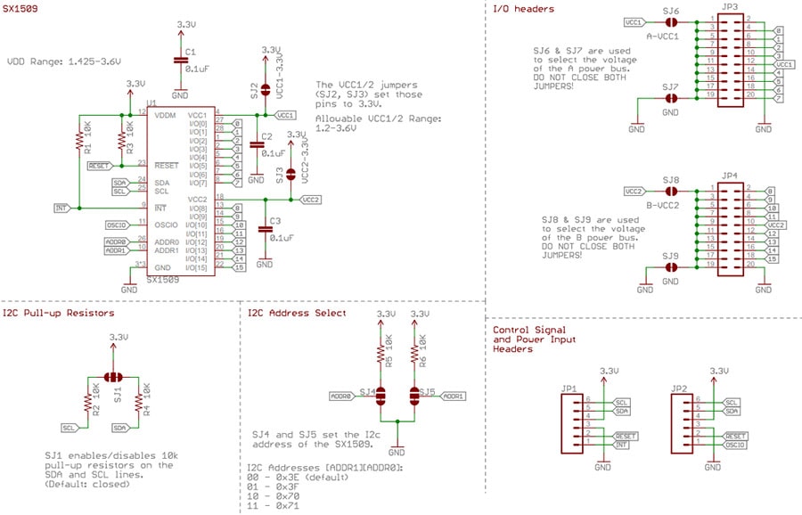
16 Output I/O Expander Breakout Schematic:
Getting Started with the 16 Output I/O Expander Breakout Board:
The SX1509 is a 16-channel GPIO expander with an I2C interface -- that means with just two wires, your microcontroller can interface with 16 fully configurable digital input/output pins.
But, the SX1509 can do so much more than just simple digital pin control. It can produce PWM signals, so you can dim LEDs. It can be set to blink or even breathe pins at varying rates. And, with a built-in keypad engine, it can interface with up to 64 buttons set up in an 8x8 matrix.
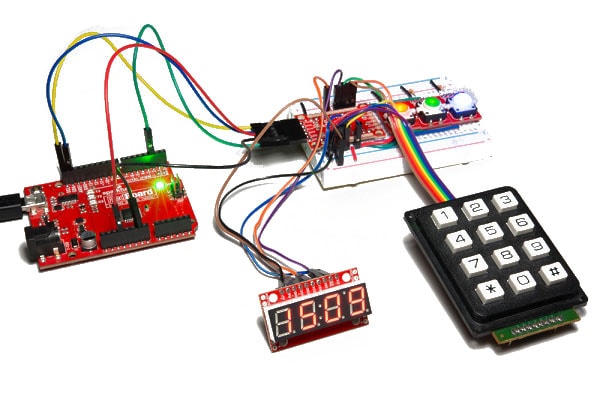
Here you can see the SX1509 controlling three LEDs, monitoring three buttons and a 12-button keypad, and producing SPI signals to drive a Serial 7-Segment Display:
16 Output I/O Expander Breakout Board and Pin Layout:
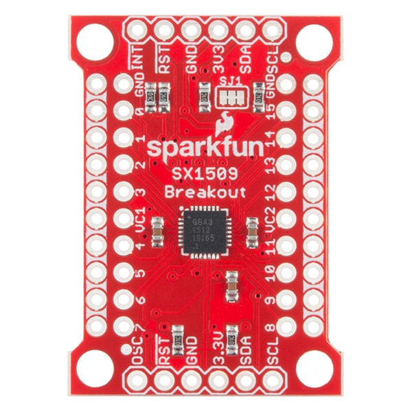
| Pin Label | Type | Description |
|---|---|---|
| INT | Output | Active low programmable interrupt |
| RST | Input | Active low reset (pulled high on-board) |
| GND | Power | Ground (0V) |
| 3V3 | Power | Main supply voltage (1.425-3.6V) |
| SDA | I2C | I2C serial data line |
| SCL | I2C | I2C serial clock line |
| OSC | Clock In/Out | Optional clock input, or programmable clock signal output |
The SX1509 breaks its 16 I/O into two banks -- bank A and bank B. Each bank can operate on a separate power supply, but by default, they're both set to 3.3V. Bank A is powered by VCC1, and bank B is supplied by VCC2. VCC1 and VCC2 can range between 1.2V and 3.6V if you want to supply them externally. Check out the "Jumpers" section for more information on that.
Every I/O pin is capable of PWM and blink outputs, but only half of them can be set to "breathe" (blink with smooth transitions from on to off). Also, if you plan on using the SX1509 keypad driver, each I/O is relegated to either a row or column interface.
| LED Driver | Keypad | ||||
| I/O | PWM | Blink | Breathe | Row | Column |
| 0 | ✓ | ✓ | ✓ | ||
| 1 | ✓ | ✓ | ✓ | ||
| 2 | ✓ | ✓ | ✓ | ||
| 3 | ✓ | ✓ | ✓ | ||
| 4 | ✓ | ✓ | ✓ | ✓ | |
| 5 | ✓ | ✓ | ✓ | ✓ | |
| 6 | ✓ | ✓ | ✓ | ✓ | |
| 7 | ✓ | ✓ | ✓ | ✓ | |
| 8 | ✓ | ✓ | ✓ | ||
| 9 | ✓ | ✓ | ✓ | ||
| 10 | ✓ | ✓ | ✓ | ||
| 11 | ✓ | ✓ | ✓ | ||
| 12 | ✓ | ✓ | ✓ | ✓ | |
| 13 | ✓ | ✓ | ✓ | ✓ | |
| 14 | ✓ | ✓ | ✓ | ✓ | |
| 15 | ✓ | ✓ | ✓ | ✓ | |
Connecting the I/O Expander Breakout Board to an Arduino:
Here's a quick example that shows how you can digitalWrite or digitalRead using the SX1509.
Connect your circuit as below: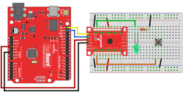
Match up 3.3V, GND, SDA, and SCL between your Arduino and the SX1509 Breakout. Then connect an LED to I/O 15 -- you can either configure it to source or sink current. And connect an active-low button to I/O.
Example Code for using IO Expander with Arduino:
You'll want to download the Arduino library from the Documents section below and install.
[code language="language"]
#include // Include the I2C library (required)
#include // Include SX1509 library
SX1509 io; // Create an SX1509 object
// SX1509 pin definitions:
// Note: these aren't Arduino pins. They're the SX1509 I/O:
const int SX1509_LED_PIN = 15; // LED connected to 15 (source ing current)
const int SX1509_BTN_PIN = 7; // Button connected to 0 (active-low)
bool ledState = false;
void setup()
{
pinMode(13, OUTPUT); // Use pin 13 LED as debug output
digitalWrite(13, LOW); // Start it as low
// Call io.begin() to initialize the I/O
// expander. It'll return 1 on success, 0 on fail.
if (!io.begin(0x3E))
{
// If we failed to communicate, turn the pin 13 LED on
digitalWrite(13, HIGH);
while (1)
; // And loop forever.
}
// Call io.pinMode(, ) to set any SX1509 pin as
// either an INPUT, OUTPUT, INPUT_PULLUP, or ANALOG_OUTPUT
io.pinMode(SX1509_LED_PIN, OUTPUT);
io.pinMode(SX1509_BTN_PIN, INPUT_PULLUP);
// Blink the LED a few times before we start:
[/code]
Documents:
- SX1509 Datasheet
- SX1509 Arduino Library (Sparkfun)
Related Products

HDMI Plug Breakout Board
AdaFruit


Breakout Board for microSD Transflash
Proto-PIC


Gas Sensor Breakout Board
Proto-PIC

ESP8266 SMT Breakout board
Proto-PIC


RJ11 Breakout Board (BOB-14021)
Sparkfun