


Description
555 Timer IC - DIP-8
This is a common 555 timer/oscillator from TI. A classic for all of those first-year circuits/projects where you need to blink an LED, generate tone, and thousands of other great beginning projects. These devices are precision timing circuits capable of producing accurate time delays or oscillation. In the time-delay or monostable mode of operation, the timed interval is controlled by a single external resistor and capacitor network.
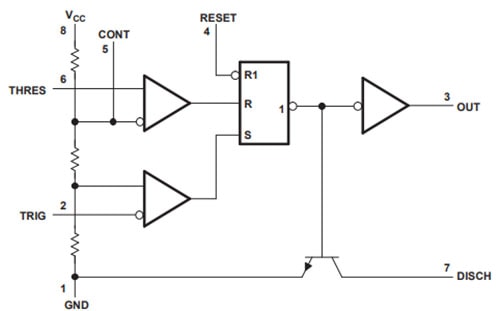
In the astable mode of operation, the frequency and duty cycle can be controlled independently with two external resistors and a single external capacitor. The threshold and trigger levels normally are two-thirds and one-third, respectively, of VCC. These levels can be altered by the use of the control voltage terminal. When the trigger input falls below the trigger level, the flip-flop is set, and the output goes high. If the trigger input is above the trigger level and the threshold input is above the threshold level, the flip-flop is reset and the output is low.
The reset (RESET) input can override all other inputs and can be used to initiate a new timing cycle. When RESET goes low, the flip-flop is reset, and the output goes low. When the output is low, a low-impedance path is provided between discharge (DISCH) and ground. The output circuit is capable of sinking or sourcing current up to 200 mA. Operation is specified for supplies of 5 V to 15 V. With a 5-V supply, output levels are compatible with TTL input
Features:
- 4.5V to 16V supply
- 8-pin DIP package
- Timing from microseconds to hours
- Astable or monostable operation
- Adjustable duty cycle
- TTL compatible output
- Sink or source up to 200mA
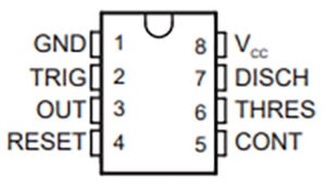
Device Pin Out:
Functional Diagram:
Getting Started:
Below we've laid out many of the circuits that you can build with a 555 timer. All you'll need to get started are some resistors, capacitors, a bread-board and a power supply.
Monostable Operation:
For monostable operation, any of these timers can be connected as shown below. If the output is low, the application of a negative-going pulse to the trigger (TRIG) sets the flip-flop (Q goes low), drives the output high, and turns off Q1.
Capacitor C then is charged through RA until the voltage across the capacitor reaches the threshold voltage of the threshold (THRES) input. If TRIG has returned to a high level, the output of the threshold comparator resets the flip-flop (Q goes high), drives the output low, and discharges C through Q1.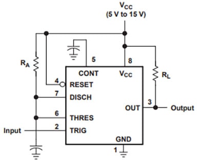
Monostable operation is initiated when TRIG voltage falls below the trigger threshold. Once initiated, the sequence ends only if TRIG is high at the end of the timing interval. Because of the threshold level and saturation voltage of Q1, the output pulse duration is approximately tw = 1.1RAC. Shown below is a plot of the time constant for various values of RA and C. The threshold levels and charge rates both are directly proportional to the supply voltage, VCC. The timing interval is, therefore, independent of the supply voltage, so long as the supply voltage is constant during the time interval.
Applying a negative-going trigger pulse simultaneously to RESET and TRIG during the timing interval discharges C and reinitiates the cycle, commencing on the positive edge of the reset pulse. The output is held low as long as the reset pulse is low. To prevent false triggering, when RESET is not used, it should be connected to VCC.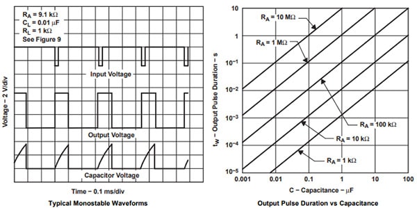
Astable Operation:
As shown in the circuit below, by adding a second resistor, RB, to the monostable circuit and connecting the trigger input to the threshold input causes the timer to self-trigger and run as a multivibrator.
The capacitor C charges thus through RA and RB and then discharges through RB only. Therefore, the duty cycle is controlled by the values of RA and RB.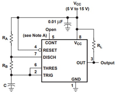
This astable connection results in capacitor C charging and discharging between the threshold-voltage level (≈0.67 × VCC) and the trigger-voltage level (≈0.33 × VCC). As in the monostable circuit, charge, and discharge times (and, therefore, the frequency and duty cycle) are independent of the supply voltage.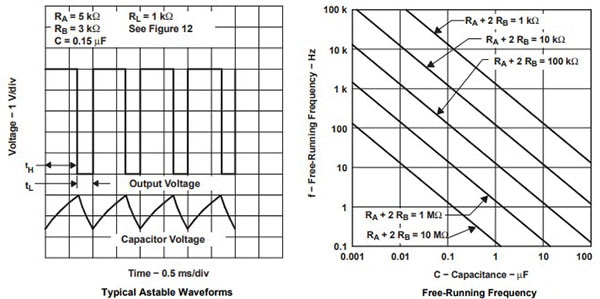
Missing-Pulse Detector:
The circuit shown in below can be used to detect a missing pulse or abnormally long spacing between consecutive pulses in a train of pulses. The timing interval of the monostable circuit is retriggered continuously by the input pulse train as long as the pulse spacing is less than the timing interval. A longer pulse spacing, missing pulse, or terminated pulse train permits the timing interval to be completed, thereby generating an output pulse as shown also below.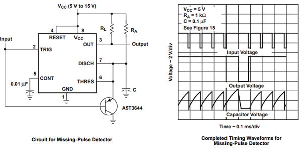
Frequency Divider:
By adjusting the length of the timing cycle on the basic monostable circuit, you can change the 555 timer to operate as a frequency divider. The chart below shows a divide-by-three circuit that makes use of the fact that retriggering cannot occur during the timing cycle.
Divide by three circuit waveforms: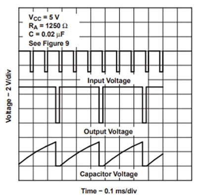
Pulse-Width Modulation:
The operation of the timer can be modified by modulating the internal threshold and trigger voltages, which is accomplished by applying an external voltage (or current) to CONT. The circuit below is configured pulse-width modulation.
A continuous input pulse train triggers the monostable circuit, and a control signal modulates the threshold voltage. Figure 19 shows the resulting output pulse-width modulation. While a sine-wave modulation signal is shown, any wave shape could be used.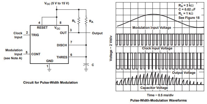
Note: The modulating signal can be direct or capacitively coupled to CONT. For direct coupling, the effects of modulation source voltage and impedance on the bias of the timer should be considered.
Pulse-Position Modulation:
In the below circuit you can see that any of these timers can be used as a pulse-position modulator. This application modulates the threshold voltage and, thereby, the time delay, of a free-running oscillator. Below you can see a triangular-wave modulation signal for such a circuit; however, any wave shape could be used.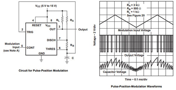
Dimensions (DIP-8):

Additional Information
Brand: |
Texas Instruments |
Part Number: |
TLC555 |
Barcode: |
5055421010096 |
Related Products

NE 556 IC OSC Timer dual 14-DIP
Proto-PIC


IC Socket Swiss Pin 8 Pin DIP 0.3"
Proto-PIC


DIP Switch - 8 Position
Sparkfun

SOIC to DIP Adapter 8-Pin
Proto-PIC


IC Socket Swiss Pin 18 Pin DIP 0.3"
Proto-PIC