Sparkfun
Graphic Equalizer Display Filter - MSGEQ7 - Seven Band

- SKU:
- PPCOM-10468


Description
Graphic Equalizer Display Filter - MSGEQ7 - Seven Band - SparkFun COM-10468
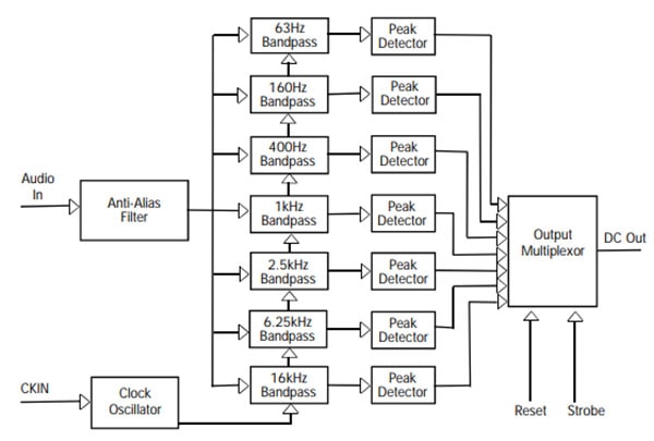
The seven-band graphic equalizer IC is a CMOS chip that divides the audio spectrum into seven bands. 63Hz, 160Hz, 400Hz, 1kHz, 2.5kHz, 6.25kHz, and 16kHz. The seven frequencies are peak detected and multiplexed to the output to provide a DC representation of the amplitude of each band. No external components are needed to select the filter responses. Only an off-chip resistor and capacitor are needed to select the on-chip clock oscillator frequency. The filter center frequencies track this frequency.
Other than coupling and decoupling capacitors, no other external components are needed. The chip supply can be between 2.7 and 5.5 volts with 5 volts providing the best performance. The device has a very low quiescent current (less than 1ma typical) for portable audio devices. the multiplexer is controlled by a reset and a strobe, permitting multiplexer readout with only two pins. The multiplexer readout rate also controls the decay time (10% decay per read), so no external pins are needed for this function.
Typical applications for this device include portable stereos, car stereos, Hi-Fi, and spectrum analyzers
Features:
- Low Power Consumption
- Only Two External Components
- On-Chip Ground Reference
- Switched-Capacitor Filters
- 3.3 or 5 Volts Operation
- 20 dB of Gain
- On-Chip Oscillator
- Output Multiplexer
- Variable Decay Time
- 8 Pin DIP Package
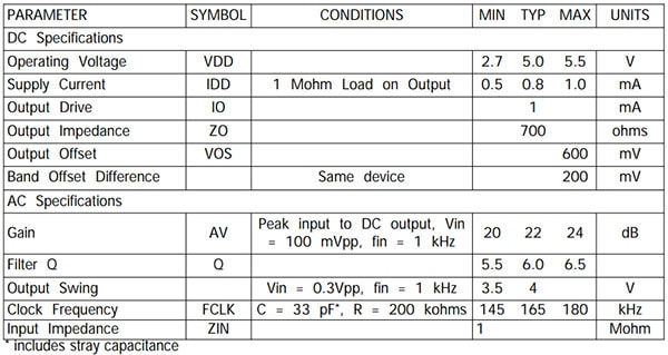
Specifications:
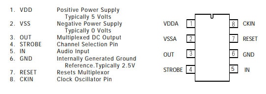
Package Pinout:
Block Diagram:
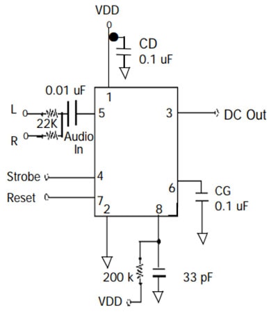
Typical Application and Circuit:
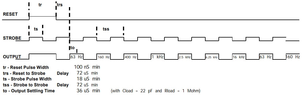
The DC peak output for measurement is selected using the reset and strobe pins. Reset high resets the multiplexor. Reset low enables the strobe pin.
After the first strobe leading edge advances the multiplexor on channel (63Hz, 160Hz, 400Hz, 1KHz, 2.5KHz, 6.25KHz, 16KHz etc.) and this will repeat indefinitely.
The multiplexor read rate is also the output decay time control. Each read decays that channel approximately 10%. As displayed below in the strobe timing diagram.
Strobe Timing Diagram:
Documents:
2 Reviews
-
Title of review 667
For a simple application using Arduino to drive a graphic equalizer display, this little chip saves a lot of time and effort. Taking the output of an electret microphone (also from Proto-Pic) through an LM358 Op-Amp, gives enough input to the MSGEQ7 to us
-
Title of review 666
A great chip, only needs a few components, all available from Proto-Pic. I soldered the circuit shown on the datasheet on a small offcut of veroboard as it acts as an input to the Arduino and does not need to be changed. I can then breadboard the output
Related Products


iPad Retina Display
AdaFruit

OLED Display 128X32 I2C
Proto-PIC


7 Segment Display - LED Matrix Backpack for 1.2" Tall 4 digit clock displays
AdaFruit


Graphic LCD 84x48 Nokia 5110 (LCD-10168)
Sparkfun
")
 size coin comparison")
7 Segment Display - 20mm (White)
Sparkfun