


Description
High-Power Stepper Motor Driver 36v4 - Pololu 3730
The Pololu High-Power Stepper Motor Driver 36v4 combines the DRV8711 stepper motor driver IC from Texas Instruments with external MOSFETs to enable control of large bipolar stepper motors at operating voltages from 8 V to 50 V. The DRV8711 has many configurable settings, so please see the DRV8711 datasheet for a detailed explanation of its features and how to use them (we also have an Arduino library that simplifies getting started by providing basic functions for configuring and operating the driver).
The driver’s power performance is a function of the external dual H-bridges, which allow the driver to deliver continuous currents up to 4 A per phase without any additional cooling such as heat sinks or forced airflow. (With sufficient additional cooling, the driver can support currents up to around 6 A per phase).
High-Power Stepper Motor Driver Features:
- Wide 8 V to 50 V operating voltage range
- High-power: can deliver up to 4 A continuous per phase without extra cooling (6 A max with sufficient additional cooling)
- Highly configurable through SPI interface
- Optional STEP/DIR control pins (stepping can also be controlled through SPI interface alone)
- Nine different step resolutions down to 256 micro-steps: full-step, half-step, 1/4-step, 1/8-step, 1/16-step, 1/32-step, 1/64-step, 1/128-step, and 1/256-step
- Adjustable current control lets you set the maximum current output, enabling the use of voltages above your stepper motor’s rated voltage to achieve higher step rates
- Adaptive blanking time, adjustable decay times, and various current decay modes enable the creation of ultra-smooth motion profiles through the SPI interface
- Optional STALL output enables stall detection when micro-stepping
- Optional BEMF output enables more advanced control and stall detection algorithms based on the back EMF of the stepper motor
- The driver supports alternate operating modes for controlling two brushed DC motors with PWM inputs instead of one bipolar stepper motor with STEP/DIR inputs
- Inputs compatible with 1.8 V, 3.3 V, and 5 V logic
- Digital outputs are all open drain with pull-ups to externally supplied IOREF voltage for use with non-5V systems (IOREF can be connected to neighboring 5V OUT pin for use with 5V systems)
- Under-voltage lockout, over-current protection, short circuit protection, and reverse-voltage protection (up to 40 V)
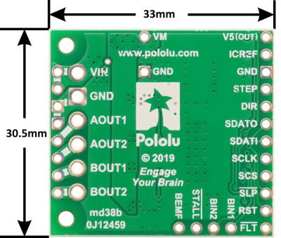
Dimensions:
- Size: 33 x 30.5 mm (1.3" x 1.2")
- Weight: 4.9 g
Included Hardware:
-
- Two 1×12-pin breakaway 0.1″ male header
- Three 2-pin, 3.5 mm terminal blocks (for board power and motor outputs)
- One 0.1″ shorting block (for optionally connecting IOREF to neighboring V5 pin when using this driver in 5 V systems)
Using the High-Power Stepper Motor Driver
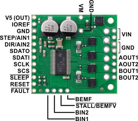
| PIN | Description |
|---|---|
| VIN | 8 V to 50 V board power supply connection (reverse-protected up to 40 V). |
| VM | This pin gives access to the motor power supply after the reverse-voltage protection MOSFET (see the board schematic at the bottom of this page). It can be used to supply reverse-protected power to other components in the system. This pin can also be used with the adjacent GND pin to add an external electrolytic capacitor in systems where additional bypass capacitance would be helpful. |
| GND | Ground connection points for the motor power supply and control ground reference. The control source and the motor driver must share a common ground. |
| AOUT1 | Motor output: “positive” end of phase A coil. |
| AOUT2 | Motor output: “negative” end of phase A coil. |
| BOUT1 | Motor output: “positive” end of phase B coil. |
| BOUT2 | Motor output: “negative” end of phase B coil. |
| V5 (OUT) | Regulated 5 V output: this pin gives access to the voltage from the internal regulator of the DRV8711. The regulator can only provide up to 10 mA, so it is primarily only useful for hard-wiring board inputs high and powering pull-ups for the board’s open-drain outputs. It is generally not intended for powering external devices. |
| IOREF | All of the board signal outputs (except BEMF) are open-drain outputs that are pulled up to IOREF, so this pin should be supplied with the logic voltage of the controlling system (e.g. 3.3 V for use in 3.3 V systems). For convenience, it can be connected to the neighboring V5 (OUT) pin when it is being used in a 5 V system. |
| STEP/AIN1 | Changes on this input move the motor current one step up or down in the translator table (even when the motor is disabled). Stepping can also be controlled through the SPI interface, so this pin is optional. In external PWM mode, this pin functions as AIN1 rather than STEP and directly controls the state of the AOUT1 output. |
| DIR/AIN2 | Input that determines the direction of stepper motor rotation. The direction can also be controlled through the SPI interface, so this pin is optional. In external PWM mode, this pin functions as AIN2 rather than DIR and directly controls the state of the AOUT2 output. |
| SDATO | SPI data output. (This pin is also often referred to as “MISO”.) This pin is an open-drain output and is pulled up to IOREF on the board. |
| SDATI | SPI data input. (This pin is also often referred to as “MOSI”.) |
| SCLK | SPI clock input. |
| SCS | SPI chip select input. Logic transitions on this pin are required for SPI communication, even if this is the only device on the SPI bus. |
| SLEEP | By default, the driver pulls this pin low, which puts it in a low-power sleep mode where the motor driver circuitry is disabled and all analog circuitry is placed into a low-power state. The digital circuitry still operates in sleep mode, so the device registers can still be accessed via the serial interface. This pin must be driven high to enable the device. |
| RESET | Chip reset input. A logic high on this input resets all internal logic, including the indexer and device registers, and disables the driver outputs. Note: the RESET pin does not function while the device is in sleep mode. |
| FAULT | Open-drain output that drives low when an over-current, pre-driver, over-temperature, or under-voltage fault is occurring. This pin is pulled up to IOREF, making it high by default. |
| BIN1 | In external PWM mode, BIN1 directly controls the state of the BOUT1 output. This pin is not used in indexer mode (i.e. when using this device as a stepper motor driver). |
| BIN2 | In external PWM mode, BIN2 directly controls the state of the BOUT2 output. This pin is not used in indexer mode (i.e. when using this device as a stepper motor driver). |
| STALL/BEMFV | Open-drain output that is pulled up to IOREF on the board. In internal stall detect mode, output goes low when stall is detected. In external stall detect mode, output goes low when valid back EMF measurement is available. |
| BEMF | Analogue output that represents the motor back EMF. The signal on this pin can be further processed by a microcontroller to implement more advanced control and stall detection algorithms. |
At high input voltages (especially above 30 V) and high current limits, the driver’s SPI interface is more likely to be affected by electrical noise from the driver and stepper motor, potentially leading to communication errors. You can reduce this interference with careful wiring and shielding, and you can lower the risk of unexpected behavior by taking appropriate precautions with SPI communication (for example, read and verify configuration settings after writing them, and avoid configuring the driver while the motor outputs are enabled).
Typical wiring (5 V systems only):
The High-Power Stepper Motor Driver 36v4 has an internal 5 V regulator that can be used to supply IOREF in cases where the board is being used in 5 V systems. We provide a shorting block for connecting V5 to IOREF, or for a more compact connection, you can bridge the surface mount jumper located next to those pins (highlighted in the picture below).
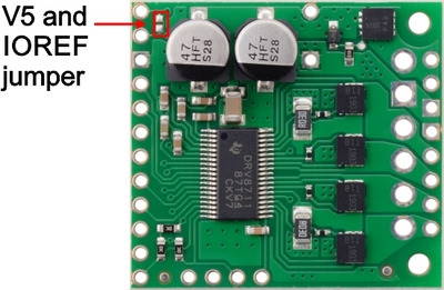 |
| Surface mount jumper for V5 and IOREF pins on the Pololu High-Power Stepper Motor Driver 36v4. |
|---|
Power Dissipation Considerations:
The High-Power Stepper Motor Driver 36v4 can deliver up to 4 A continuous per phase under typical conditions, but the actual current it can deliver will depend on how well you can keep the module cool. The driver’s printed circuit board is designed to draw heat out of the MOSFETs, but performance can be improved by adding a heat sink or forced airflow. (Conversely, performance will be reduced in applications that limit heat dissipation, such as high ambient temperatures or operation in enclosures.) With sufficient additional cooling, the driver can deliver up to 6 A per phase before exceeding the 1 W power ratings of the 30 mΩ current sense resistors.
The driver’s current limit is set through its SPI interface. You can confirm you have set it correctly by using a multimeter to measure the actual current through one of the coils while the stepper motor is in full-step mode and not stepping. The current you measure this way will be approximately 70% of the set limit. Please note that measuring the current draw at the power supply will generally not provide an accurate measure of the coil current. Since the input voltage to the driver can be significantly higher than the coil voltage, the measured current on the power supply can be quite a bit lower than the coil current (the driver and coil basically act like a switching step-down power supply). Also, if the supply voltage is very high compared to what the motor needs to achieve the set current, the duty cycle will be very low, which also leads to significant differences between average and RMS currents.
Warning: This motor driver has no meaningful over-temperature shut-off (while the DRV8711 IC has over-temperature protection, it is the external MOSFETs that will overheat first). An over-temperature condition can cause permanent damage to the motor driver. We strongly recommend you do not increase the current limit setting beyond 4 A (or lower in applications with reduced heat dissipation) unless you can first confirm that the temperature of the MOSFETs will stay under 140°C.
Note: When the driver powers up, the current limit setting defaults to the maximum (~18 A). Make sure you set it to something appropriate for both your stepper motor and the driver before activating the outputs!
This product can get hot enough to burn you long before the chip overheats. Take care when handling this product and other components connected to it.
High-Power Stepper Motor Driver Documents:
- Schematic diagram of the Pololu High-Power Stepper Motor Driver 36v4 (117k pdf)
- Dimension diagram of the Pololu High-Power Stepper Motor Driver 36v4 (320k pdf)
- 3D model of the Pololu High-Power Stepper Motor Driver 36v4 (7MB step)
- Drill guide for the Pololu High-Power Stepper Motor Driver 36v4 (81k dxf)
- DRV8711 Stepper Motor Controller IC datasheet
- Arduino library for the Pololu High-Power Stepper Motor Driver
- DRV8711 Decay Mode Setting Optimization Guide
- DRV8711 documentation
Related Products


Stepper Motor, 400 Steps, 58 oz.in, Nema 17 (ROB-10846)
Sparkfun

378:1 Metal Gearmotor 25Dx73L mm LP 12V with 48 CPR Encoder
Pololu


Stepper Motor: Bipolar, 200 Steps/Rev, 28+ù32mm, 3.8V, 0.67 A/Phase
Pololu