


Description
Large Digit Driver for 7-Segment Display
SparkFun WIG-13279
The SparkFun Large Digit Driver is a chainable controller backpack that can be soldered directly to the back of our large 6.5" 7-segment displays. Large numerical displays are a great addition to any project where you want to be able to see information at a distance.
The SparkFun Large Digit Driver can easily be attached to the back of the 7-segment display by soldering all 10 castellations pins at the bottom of the board as well as the two additional castellations at the top.
It is worth noting that the Large Digit Driver requires 12V for the LEDs and also a 5V supply for the onboard shift register IC.
Each driver is equipped with six input pins and six output pins, these make the driver capable of being chained together. The input/output pins are listed as GND (Ground), LAT (Latch), CLK (Clock), SER (Serial), 5V (Power for the driver IC), and 12V (Power for the 7-segment display). We actually used the SparkFun Large Digit Driver in our AVC Battle-Bot Arena to display times and scores!
The large 7-segment LED displays can make for superb scorekeepers and lap timers.
Large Digit Driver Features:
- Operating Voltage: 5V
- Chainable to another Large Digit Driver
- Attaches directly to the 7-Segment Display
- castellated Mounting Holes
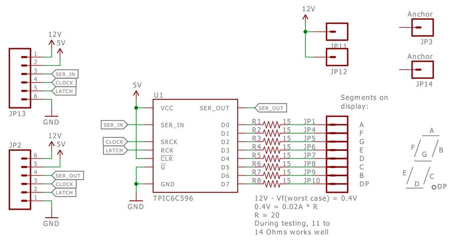
Large Digit Driver Schematic:
Getting Started with the Large Digit Driver:
You'll want to get yourself a few things ready before you start. Firstly a 7 segment display, and if you plan to connect using a cable, some 6 pin jumper wires will come in handy. You can chop these in half, and solder the wires directly to the display.
Alternatively, the Large Digit Driver can be soldered directly to the Display as shown below.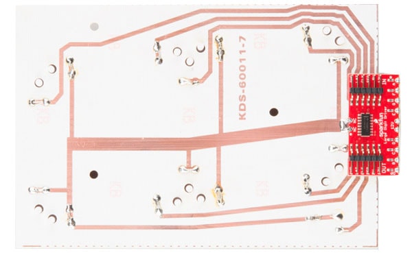
Several Large Digit Drivers can be chained together to create a display with multiple digits.
Before Fitting to Display:
Before you attach the Large Digit Driver to the 7-segment display, you will need to isolate the exposed vias on the back of the board. Some of the Driver boards are created with through-hole vias that are not covered with solder mask. As a result, this could likely short out the traces on the back of the 7-segment display.
We recommend using a piece of high temperature tape to cover the vias on the back of the Driver board as below.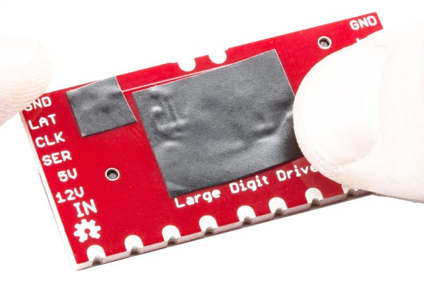
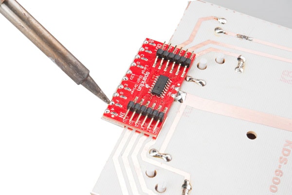
You will need to solder the Large Digit Driver to the back of the 7-segment display. Have the Driver's 10 pins facing toward the bottom of the large 7-segment display and lined up with the traces on the back of the 7-segment display. Solder all 10 of the castellations as well as the 2 castellations at the top of the board (these should be attached to the 12V line and are just for mechanical support).
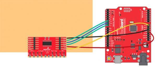
Connecting the Large Digit Driver to Arduino:
We will be using the Arduino's regulated 5V and unregulated 12V (from the wall adapter) to power the 7-segment display and Large Digit Driver.
| Large Digit Driver | Arduino |
|---|---|
| GND | GND |
| LAT | 5 |
| CLK | 6 |
| SER | 7 |
| 5V | 5V |
| 12V | VIN |
Example Arduino Code for the Large Digit Driver:
[code language="arduino"]
/*
Controlling large 7-segment displays
By: Nathan Seidle
SparkFun Electronics
Date: February 25th, 2015
License: This code is public domain but you buy me a beer if you use this and we meet someday (Beerware license).
The large 7 segment displays can be controlled easily with a TPIC6C594 IC. This code demonstrates how to control
one display.
Here's how to hook up the Arduino pins to the Large Digit Driver
Arduino pin 6 -> CLK (Green on the 6-pin cable)
5 -> LAT (Blue)
7 -> SER on the IN side (Yellow)
5V -> 5V (Orange)
Power Arduino with 12V and connect to Vin -> 12V (Red)
GND -> GND (Black)
There are two connectors on the Large Digit Driver. 'IN' is the input side that should be connected to
your microcontroller (the Arduino). 'OUT' is the output side that should be connected to the 'IN' of addtional
digits.
Each display will use about 150mA with all segments and decimal point on.
*/
//GPIO declarations
//-=-=-=-=-=-=-=-=-=-=-=-=-=-=-=-=-=-=-=-=-=-=-=-=
byte segmentClock = 6;
byte segmentLatch = 5;
byte segmentData = 7;
//-=-=-=-=-=-=-=-=-=-=-=-=-=-=-=-=-=-=-=-=-=-=-=-=
void setup()
{
Serial.begin(9600);
Serial.println("Large Digit Driver Example");
pinMode(segmentClock, OUTPUT);
pinMode(segmentData, OUTPUT);
pinMode(segmentLatch, OUTPUT);
digitalWrite(segmentClock, LOW);
digitalWrite(segmentData, LOW);
digitalWrite(segmentLatch, LOW);
int x = 0;
while(1)
{
if(x == 9)
postNumber(x, true); //Show decimal
else
postNumber(x, false);
digitalWrite(segmentLatch, LOW);
digitalWrite(segmentLatch, HIGH); //Register moves storage register on the rising edge of RCK
delay(500);
x++;
x %= 10; //Reset x after 9
Serial.println(x); //For debugging
}
}
void loop()
{
//showNumber(42); //Test pattern
}
//Takes a number and displays 2 numbers. Displays absolute value (no negatives)
void showNumber(float value)
{
int number = abs(value); //Remove negative signs and any decimals
//Serial.print("number: ");
//Serial.println(number);
for (byte x = 0 ; x < 2 ; x++)
{
int remainder = number % 10;
postNumber(remainder, false);
number /= 10;
}
//Latch the current segment data
digitalWrite(segmentLatch, LOW);
digitalWrite(segmentLatch, HIGH); //Register moves storage register on the rising edge of RCK
}
//Given a number, or '-', shifts it out to the display
void postNumber(byte number, boolean decimal)
{
// - A
// / / F/B
// - G
// / / E/C
// -. D/DP
#define a 1<<0
#define b 1<<6
#define c 1<<5
#define d 1<<4
#define e 1<<3
#define f 1<<1
#define g 1<<2
#define dp 1<<7
byte segments;
switch (number)
{
case 1: segments = b | c; break;
case 2: segments = a | b | d | e | g; break;
case 3: segments = a | b | c | d | g; break;
case 4: segments = f | g | b | c; break;
case 5: segments = a | f | g | c | d; break;
case 6: segments = a | f | g | e | c | d; break;
case 7: segments = a | b | c; break;
case 8: segments = a | b | c | d | e | f | g; break;
case 9: segments = a | b | c | d | f | g; break;
case 0: segments = a | b | c | d | e | f; break;
case ' ': segments = 0; break;
case 'c': segments = g | e | d; break;
case '-': segments = g; break;
}
if (decimal) segments |= dp;
//Clock these bits out to the drivers
for (byte x = 0 ; x < 8 ; x++)
{
digitalWrite(segmentClock, LOW);
digitalWrite(segmentData, segments & 1 << (7 - x));
digitalWrite(segmentClock, HIGH); //Data transfers to the register on the rising edge of SRCK
}
}
[/code]
Large Digit Driver Documents:
Videos
View AllClose
1 Review
-
Title of review 1115
Great product for large digit displays. Easy to use and work well
Related Products
 Large Display main")
 Large Display dimension front")
Large 7 Segment Display - Red 15cm (6.5")
Sparkfun


SparkFun COM-08546 7-Segment Red LED
Sparkfun


7 Segment Display - 4 digit - Yellow
Sparkfun


7 segment Display - 4 didgit Blue
Sparkfun