Sparkfun
Stepper Motor Driver - SparkFun ProDriver - (TC78H670FTG)
 main")
- SKU:
- PPROB-16836
 main")
 main 1")
 rear")
 main")
 main 1")
 rear")
Description
Stepper Motor Driver - SparkFun ProDriver - (TC78H670FTG)
The SparkFun ProDriver makes it easy to start developing with the TC78H670FTG bipolar stepper motor driver from Toshiba! Latch terminals provide instant solder-less connections to every feature offered. This a great option for any project requiring precision motor control.
In addition to high-resolution control (down to 1/128th of a step), the ProDriver can be controlled via traditional clock-in stepping or serial commands. Both methods are demonstrated in the Arduino Library. The serial command method is especially unique in that it allows the user to precisely control the phase, torque, current limit, and mixed decay ratio of each coil immediately during stepping. Most stepper motor driver ICs require using an external trimpot to set the current limit, but with the ProDriver, you can precisely adjust this via serial commands!
ProDriver Features:
- Toshiba TC78H670FTG Clock-in and Serial controlled Bipolar Stepping Motor Driver
- Latch terminals for plug and play access (no soldering required!)
- Allows full, half, quarter, 1/8, 1/16, 1/32, 1/64, 1/128 step operation
- Power supply operating voltage: 3.6 V to 16.0 V
- Output current ratings: 2.0 A (max)
- Additional over current protection provided by an on-board PTC
- Multi error detect functions (Thermal shutdown (TSD), Over current (ISD), motor load open (OPD) and Under voltage lockout (UVLO))
- Exposed copper for optional bottom-side heat sink
- Extensive Arduino Library support with 10 examples!
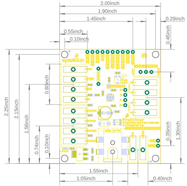
ProDriver Board Dimensions:
- Board Length: 57.2mm (2.25")
- Board Width: 50.8mm (2")
Sparkfun ProDriver Schematic:
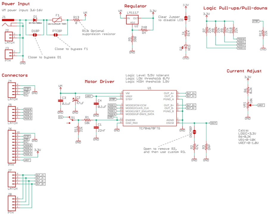
Sparkfun ProDriver Documents:
- TC78H670FTG Datasheet (Clock-in and Serial controlled Bipolar Stepping Motor Driver)
- SparkFun ProDriver TC78H670FTG Arduino Library and Example Code
Connecting up the ProDriver:
Power - You'll need a power supply that has an output of 3.3 - 16V and can source at least 2A. We have provided three different methods for users to connect their power supply to the ProDriver:
- A 5.5 x 2.1 mm DC barrel jack, which is simple and the easiest to use.
- A latch pin terminal that is similar to a screw terminal, except toolless.
- A set of PTH points (
VMandGND) for users who wish to, more permanently, solder their power connections.
Power Note: Do not connect or disconnect the motor while the ProDriver is powered; as it may damage the ProDriver.
Input Control Pins - The input control pins are used to interface directly with the TC78H670FTG motor driver. The ProDriver was designed with clever latch pins to provide a completely solderless connection to get users up and running faster. The same connections are also available via Plated Through Holes for any more permanent installations.
Output Channel Pins - The output channel pins are used to drive the coils of the stepper motor. The paired outputs are connected to the two H-Bridges of the motor driver.
H-Bridge Power Control - The
EN pin controls the ON/OFF operation of the H-Bridges to the motor outputs. When the EN pin is low, all of the H-Bridge MOSFETs turn off and become high impedance (Hi-Z). Likewise, when the EN pin is set high, the motor channel outputs will be driven normally, based on the stepping controls.
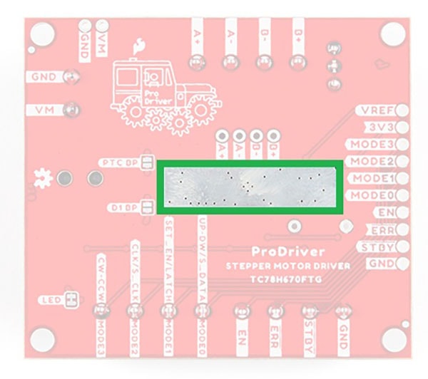
Heat Sink - There is a thermal ground plane on the bottom of the board available for users to attach a heat sink(s) with some thermal tape, if necessary. However, after several tests by the engineer for this product, we have determined that for most use cases, a heat sink probably won't be necessary. The thermal ground planes on the bottom of the ProDriver as seen below:

Related Products


Stepper Motor Driver - Sparkfun AutoDriver (v13) (BOB-13752)
Sparkfun


Stepper Motor Driver Carrier STSPIN820
Pololu

L293D Stepper Motor Driver IC
Proto-PIC


A4988 Stepper Motor Driver Carrier
Pololu

