


Description
Stepper Motor Driver Carrier STSPIN820 - Pololu 2878
This product is a carrier board or breakout board for the STSPIN820 stepper motor driver from STMicroelectronics (ST); we therefore recommend careful reading of the STSPIN820 datasheet (594k pdf) before using this product. This stepper motor driver offers microstep resolutions down to 1/256 of a step, and it lets you control one bipolar stepper motor at up to approximately 0.9 A per phase continuously without a heat sink or forced air flow (see the Power dissipation considerations section below for more information).
This product ships with all surface-mount components—including the STSPIN820 driver IC—installed as shown in the product picture.
General Specifications:
| Motor driver: | STSPIN820 |
|---|---|
| Minimum operating voltage: | 7 V |
| Maximum operating voltage: | 45 V |
| Continuous current per phase: | 0.9 A |
| Maximum current per phase: | 1.5 A |
| Minimum logic voltage: | 2 V |
| Maximum logic voltage: | 5.5 V |
| Microstep resolutions: | full, 1/2, 1/4, 1/8, 1/16, 1/32, 1/128, 1/256 |
| Current limit control: | potentiometer |
| Reverse voltage protection?: | N |
| Header pins soldered?: | N |
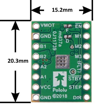
Dimensions:
- Size: 15.2 x 20.3 mm (0.6" x 0.8")
- Weight: 1.4 g
Included hardware:
The STSPIN820 stepper motor driver carrier ships with one 1×16-pin breakaway 0.1″ male headers. The headers can be soldered in for use with solderless breadboards or 0.1″ female connectors. You can also solder your motor leads and other connections directly to the board.
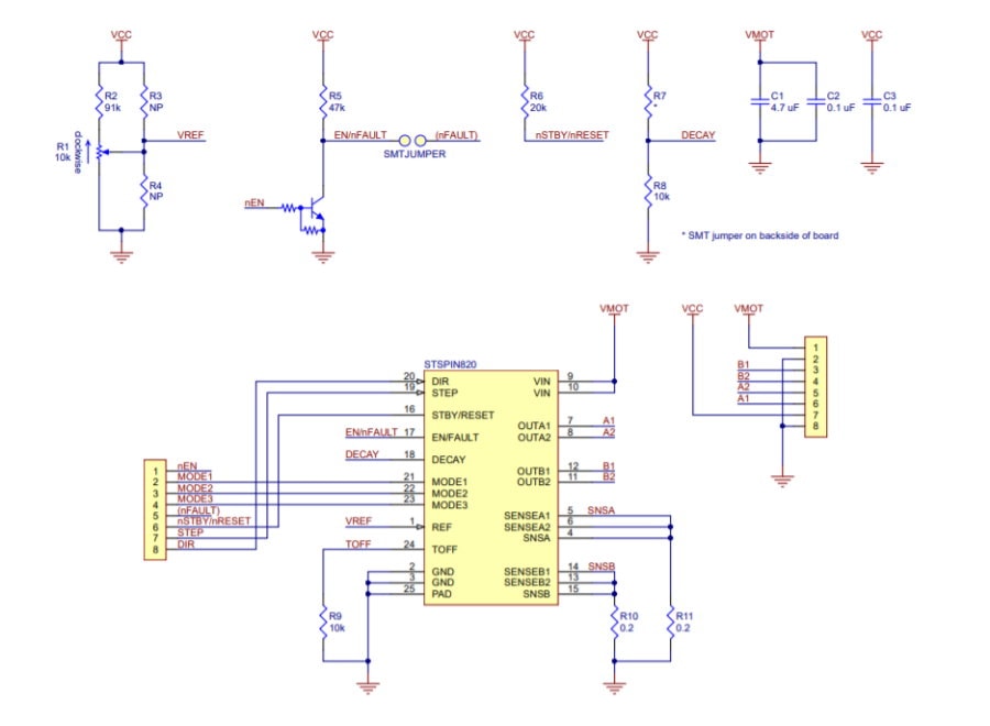
Schematic Diagram:
Using the driver:
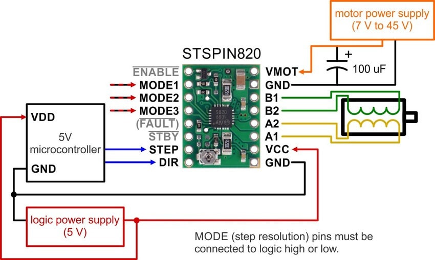
Minimal wiring diagram for connecting a microcontroller to a STSPIN820 stepper motor driver carrier.
Power Connections:
The driver requires a logic supply voltage (3 – 5 V) to be connected across the VCC and GND pins and a motor supply voltage of 7 V to 45 V to be connected across VIN and GND. These supplies should have appropriate decoupling capacitors close to the board, and they should be capable of delivering the expected currents (peaks up to 3 A for the motor supply).
Motor Connections:
The STSPIN820 is intended to control a single bipolar stepper motor. The two sides of one coil should be connected across OUTA1 and OUTA2, and the two sides of the other coil should be connected across OUTB1 and OUTB2.
Warning: Connecting or disconnecting a stepper motor while the driver is powered can destroy the driver. (More generally, rewiring anything while it is powered is asking for trouble.)
Step (and microstep) Size:
Stepper motors typically have a step size specification (e.g. 1.8° or 200 steps per revolution), which applies to full steps. A microstepping driver such as the STSPIN820 allows higher resolutions by allowing intermediate step locations, which are achieved by energizing the coils with intermediate current levels. For instance, driving a motor in quarter-step mode will give the 200-step-per-revolution motor 800 microsteps per revolution by using four different current levels.
The resolution (step size) selector inputs (MODE1, MODE2, and MODE3) enable selection from the eight step resolutions according to the table below. These three pins are floating, so the MODE pins must be connected to logic high or low before operating the driver. For the microstep modes to function correctly, the current limit must be set low enough (see below) so that current limiting gets engaged. Otherwise, the intermediate current levels will not be correctly maintained, and the motor will skip microsteps.
| MODE1 | MODE2 | MODE3 | Microstep Resolution |
|---|---|---|---|
| Low | Low | Low | Full step |
| High | Low | Low | Half step |
| Low | High | Low | 1/4 step |
| High | High | Low | 1/8 step |
| Low | Low | High | 1/16 step |
| High | Low | High | 1/32 step |
| Low | High | High | 1/128 step |
| High | High | High | 1/256 step |
Control Inputs and Status Outputs:
The rising edge of each pulse to the STEP (STCK) input corresponds to one microstep of the stepper motor in the direction selected by the DIR pin. Unlike most of our other stepper motor driver carriers, the STEP and DIR inputs are floating, so they must be connected to logic high or low to ensure proper operation.
The STSPIN820 IC has two different inputs for controlling its power states, STBY/RESET and EN/FAULT:
The STSPIN820 can detect several fault (error) states that it reports by driving EN/FAULT pin on the driver low. The FAULT pin is not made available by default (to avoid conflicts when using the STSPIN820 carrier as a drop-in replacement for our other stepper motor driver carriers), but it can be connected to the pin labeled “( FLT )” by bridging the surface mount jumper labeled “F” on the bottom side of the board.
On our carrier, the DECAY input is pulled down with a 10k resistor that sets the driver to mixed decay mode. The driver can be set to slow decay mode by bridging the surface mount jumper labeled “D” on the bottom side of the board.
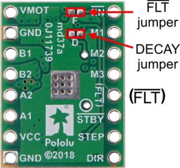
Jumpers for FLT and DECAY pins on the STSPIN820 stepper driver carrier.
Documents:
Related Products


A4988 Stepper Motor Driver Carrier
Pololu


TB67S2x9FTG Stepper Motor Driver Carriers


Stepper Motor Driver Carrier TB67S249FTG (1.7A/4.5A)
Pololu


STSPIN220 Low-Voltage Stepper Motor Driver Carrier
Pololu


Stepper Motor Driver Carrier TB67S279FTG (1.2A/2A)
Pololu