Adding an LDR to your Arduino Project

What is a Light Dependent Resistor (LDR)?
An LDR is used to detect light levels in a wide range of household and industrial projects, such as security lighting. They are in essense a variable resistor, that varies its resistance as the light intensity increases or decreases.
In the dark or at low light levels, the resistance of an LDR is higher meaning that less current can flow through it. Transversely under a bright light the resistance of an LDR is lower meaning that more current can flow through it.
These devices are super cheap, easy to use with code or without and have endless applications. We use them in our NightLight Kits!
Connecting to your Arduino:

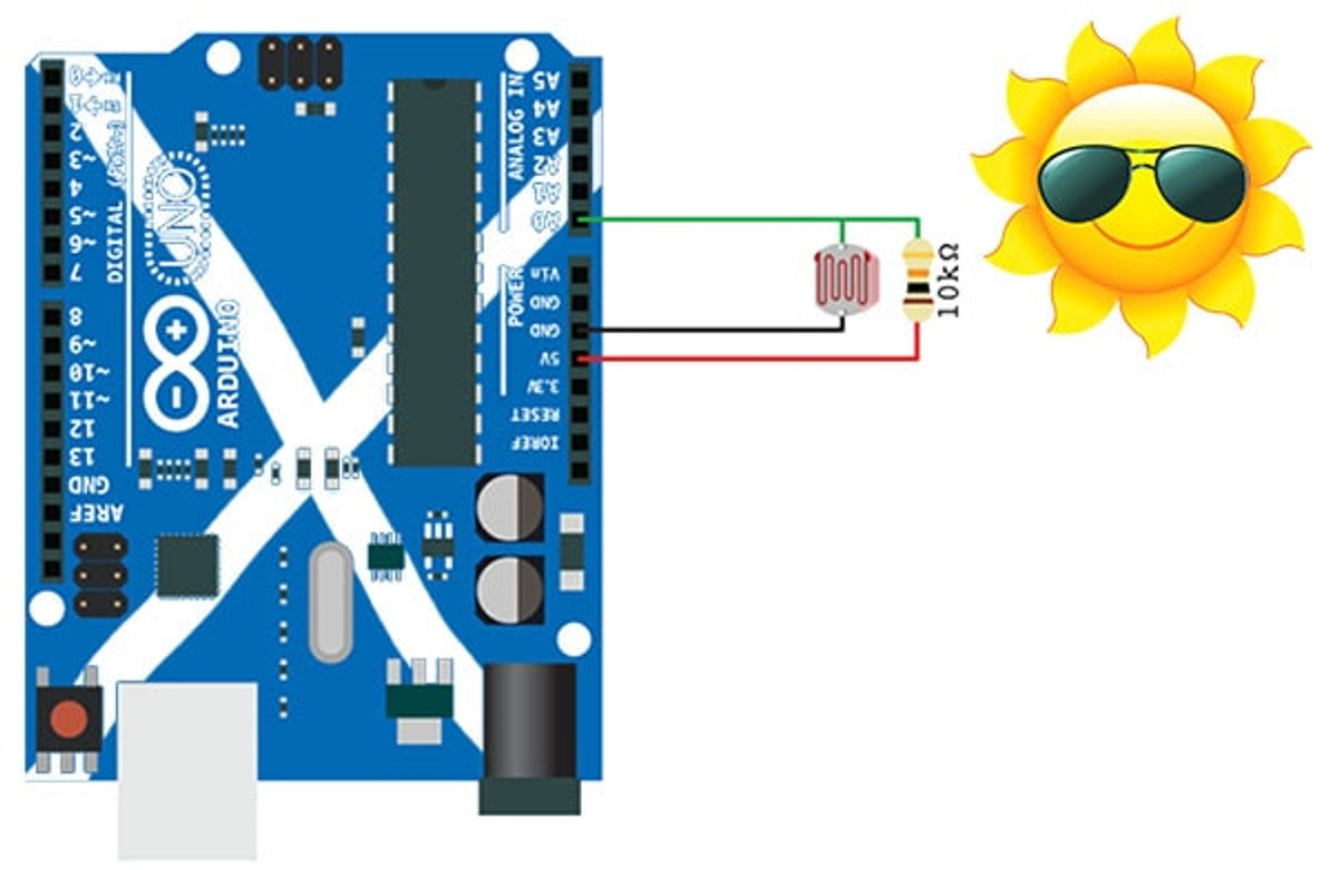
*Now we realise that this photo is not realistic or to scale... We did have to go by memory however as we've not seen the sun for a couple of years up here is Scotland!
Here you can see the LDR is connected between Ground and the Analog0 (A0) pin on the Arduino. The LDR much like a regular resistor can be used in either orientation. You'll also need to connect a fixed value resistor (we've used 10K) between the A0 pin and 5V to create a simple voltage divider circuit.
This voltage divider circuit divides the 5V between the LDR and the fixed value resistor. Meaning that when you read the voltage value on the A0 pin, you'll be able to ascertain the Resistance value of the LDR and thus the light level.
Coding your Arduino:
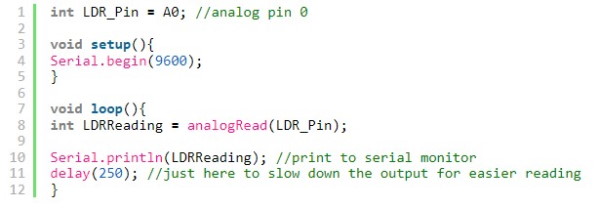
The Arduino code for this is pretty simple. You need to print to the serial monitor and add a delay if you need to see the readings, but don't worry if you don't:

Understanding the Output:
A voltage divider circuit is a very common circuit that takes a higher voltage and converts it to a lower one by using multiple resistors connected in series. The formula for calculating the output voltage is based on Ohms Law and is shown in the below equation and schematic:

Testing the LDR under a bright light in the first instance, should drive the resistance of the LDR low. A value of around 1K would be normal. This means that you should see an analogRead value of approx. 92.
In complete darkness the LDR will have a much higher resistance value (in the region of 40K), so the LDR will take a much higher proportion of the voltage. This means you would expect to see an analogRead value of approx. 818.
Have a play and see what you get!
Recent Posts
-
What is Ohm's Law?
Are you curious about how electricity works? Let me introduce you to a very important concept i …9th Mar 2023 -
How do I control a central heating system using an Arduino
To control a heating system using an Arduino, you will need to write a sketch (program) that impleme …7th Feb 2023 -
The Versatility of Slotted Aluminium Extrusions: From Robotics to Camper Van Renovations
In today's ever-evolving world, the need for versatile and adaptable building materials is greater t …25th Jan 2023


