


Description
Current Sensor Carrier -15.5A to +15.5A - ACS711EX
This board is a simple carrier of Allegro’s ±15.5 A ACS711 Hall effect-based linear current sensor with overcurrent fault output, which offers a low-resistance (~0.6 mΩ) current path and electrical isolation up to 100 V. This version accepts a bidirectional current input with a magnitude up to 15.5 A and outputs a proportional analog voltage centered at Vcc/2 with a typical error of ±5%. It operates from 3 V to 5.5 V, so it can interface directly to both 3.3 V and 5 V systems.
Overview
This current sensor is a carrier board or breakout board for Allegro’s ACS711KEXLT-15AB-T Hall effect-based linear current sensor with overcurrent fault output; we, therefore, recommend careful reading of the ACS711 datasheet before using this product. This sensor has an operating voltage of 3 V to 5.5 V and an output sensitivity of 90 mV/A when Vcc is 3.3 V (or 136 mV/A when Vcc is 5 V). The following list details some of the sensor’s key features:
- Designed for bidirectional input current from -15.5 A to 15.5 A (though the robust sensor IC can tolerate 100 ms transient current spikes up to 100 A).
- Conductive path internal resistance is typically 0.6 mΩ, and the PCB is made with 2-oz copper, so very little power is lost in the board.
- The use of a Hall effect sensor means the IC is able to electrically isolate the current path from the sensor’s electronics (for applications up to 100 V), which allows the sensor to be inserted anywhere along the current path and to be used in applications that require electrical isolation.
- 100 kHz bandwidth.
- Good accuracy and reliability: factory calibration results in a typical total output error of ±5% at room temperature, the output offset voltage is extremely stable, and the sensor has zero magnetic hysteresis.
- Overcurrent FAULT output latches low when the current magnitude exceeds 15.5 A.
- Operating temperature range of -40°C to 125°C.
The pads are labeled on the bottom silkscreen, as shown in the picture to the right. The silkscreen also shows the direction that is interpreted as a positive current flow via the +i arrow.
This 15.5 A current sensor is marked with a black X.
This sensor is very similar to our original ACS711 -12.5 to +12.5 A Current Sensor Carrier but uses a smaller “EX” package that has a larger optimized sensing range and reduced internal resistance. The board size, pinout, and hole locations are all unchanged, so it can generally be used as a drop-in replacement for our ACS711 carriers with “LC” packages.
Using the sensor
Electrical connections
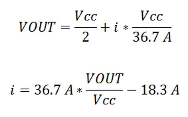
The sensor requires a supply voltage of 3 V to 5.5 V to be connected across the Vcc and GND pads, which are labeled on the bottom silkscreen. The sensor outputs an analog voltage that is linearly proportional to the input current. The quiescent output voltage is Vcc/2 and changes by 90 mV per amp of input current (when Vcc = 3.3 V), with positive current, increasing the output voltage and negative current decreasing the output voltage. The relationship between the instantaneous input current, i, and sensor output voltage, VOUT, can be represented by the following equations:
The FAULT pin is normally high and latches low when the current exceeds ±15.5 A. Once the FAULT pin is latched low, the only way to reset it is by toggling power on the Vcc pin. In our tests, this module was able to handle 15 A of continuous current without exceeding 50°C, with no cooling beyond the heat dissipation of the PCB.
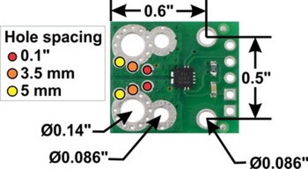
The input current can be connected to the board in a variety of ways. Holes with 0.1″, 3.5 mm, and 5 mm spacing are available as shown in the diagram above for connecting male header pins or terminal blocks. For high-current applications, you can solder wires directly to the through-holes that best match your wires, or you can use solderless ring terminal connectors, as shown in the picture above. The large through-holes are big enough for #6 screws.
Warning: This product is intended for use below 30 V. Working with higher voltages can be extremely dangerous and should only be attempted by qualified individuals with appropriate equipment and protective gear.
Mounting information
The board has two mounting holes on the logic side of the board. These mounting holes are 0.5" apart and are designed for #2 screws.
Included components
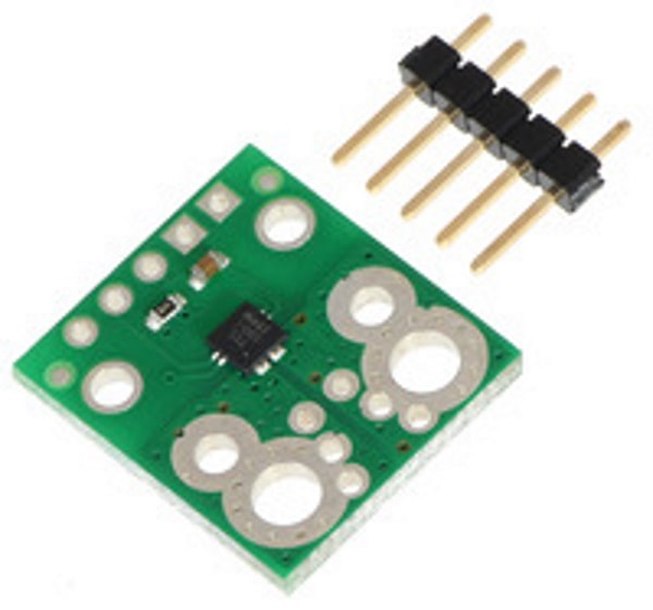
This board ships assembled with all surface mount components and a 5×1 strip of 0.1″ header pins is included but not soldered in, as shown in the picture below.
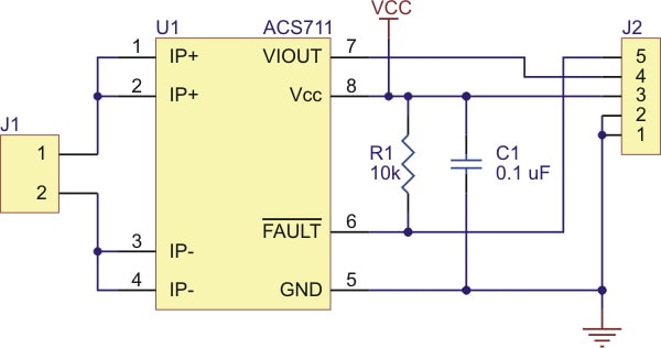
Schematic diagram
1 Review
-
Title of review 892
Product worked well out of the box. Has a good range (-15a -> +15a) and very easy to plug into an Arduino. Not a precision instrument as you might expect but does the job well.
Related Products


ACS724 Current Sensor Carrier Range


ACHS-7121 Current Sensor Carrier -10A to +10A
Pololu


Current Sensor ACS723 (Low Current) (SEN-14544)
Sparkfun


Current Sensor Breakout - INA169
Sparkfun


DRV8825 Stepper Motor Driver Carrier, High Current
Pololu