Description
FemtoBuck LED Driver - SparkFun COM-13716
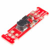
This is the FemtoBuck, a small-size single-output constant current LED driver. Each FemtoBuck has the capability to dim a single high-power channel of LEDs from 0-350mA at up to 36V while the dimming control can be either accessed via PWM or analog signal from 0-2.5V.
This board is based on the PicoBuck LED Driver, which was developed in collaboration with Ethan Zonca. Instead of blending three different LEDs on three different channels the FemtoBuck controls just one.
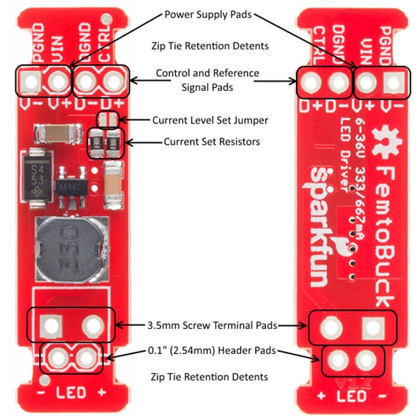
For the FemtoBuck, we’ve increased the voltage ratings on the parts to allow the input voltage to cover the full 36V range of the AL8805 driver. Since the FemtoBuck is a constant current driver, the current drawn from the supply will drop as supply voltage rises. In general, the efficiency of the FemtoBuck is around 95%, depending on the input voltage. Onboard each FemtoBuck you will find two inputs for both power input and dimming control pins and an area to install a 3.5mm screw terminal.
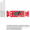
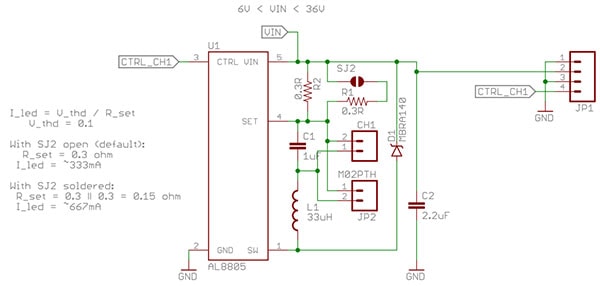
Finally, at either side of the board, you will find small indents or “ears” which will allow you to use a zip tie to secure the wires to the board after soldering them down. This version of the FemtoBuck is equipped with a small solder jumper that can be closed with a glob of solder to double the output current from 330mA to 660mA.
FemtoBuck LED Driver Schematic:
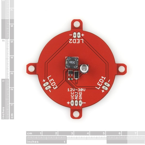
FemtoBuck LED Driver Board and Pin Layout:
Getting Started with the Femtobuck LED Driver:
You’ll want to get yourself some suitable LEDs,an Arduino, and a suitable PSU. Oh and don’t forget about wiring and soldering stuffs!
Ensuring that each channel is independently connected to the + and – connections of the LED it is to drive! Do not connect the + or – connections of any two channels together.
If you have only one or two LEDs, you can connect the FemtoBuck directly to the VIN pin on your Arduino. You will need to power the board from an external supply, as the 5V provided by USB isn't high enough to power the FemtoBuck (the FemtoBuck won't turn on below 6V).
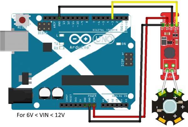
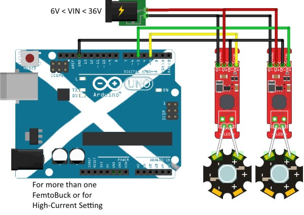
If you want more than one FemtoBuck, or if you've closed the solder jumper to increase the drive current, you'll need to add an external power supply. It's not good to try to run too much current through the traces on the Arduino. Note that the LEDs are wired separately to each FemtoBuck! This is very important; the output of each FemtoBuck must be completely isolated from any other! That means that RGB LEDs with "common" pins (common anode or common cathode) cannot be used with the FemtoBuck!
Notes:
- When using an external supply for the Femtobuck, the grounds of the two boards must be connected! If the power supply is 12V or less, the Arduino can be powered from it as well, but do not attempt to power the Femtobuck from the Arduino if you are using anything higher!
Example Arduino Code for Femtobuck:
[code language="arduino"]
const int CHL_1 = 3;
void setup()
{
pinMode(CHL_1, OUTPUT);
}
void loop()
{
// Let's just step through a couple of values, so we can see how they look.
// Remember, LEDs are non-linear, so doubling the PWM output value won't necessarily double
// the apparent brightness.
analogWrite(CHL_1, 0);
delay(1000);
analogWrite(CHL_1, 64);
delay(1000);
analogWrite(CHL_1, 255);
delay(1000);
}
[/code]
FemtoBuck LED Driver Video Introduction:
FemtoBuck LED Driver Documents:
Videos
View AllClose2 Reviews
-
Title of review 699
The Femtobuck is perfect for driving a few LEDs. It takes a DC power supply up to 35V and produces a constant current output up to 350mA. I used it to convert my 50W halogen reading lamp to an excellent 3W LED lamp using three 1W LEDs in series. My reading lamp no longer sends me to sleep with its heat.
-
Title of review 698
Does exactly what it says. Works great.


