


Description
PicoBuck LED Driver Board - SparkFun COM-13705
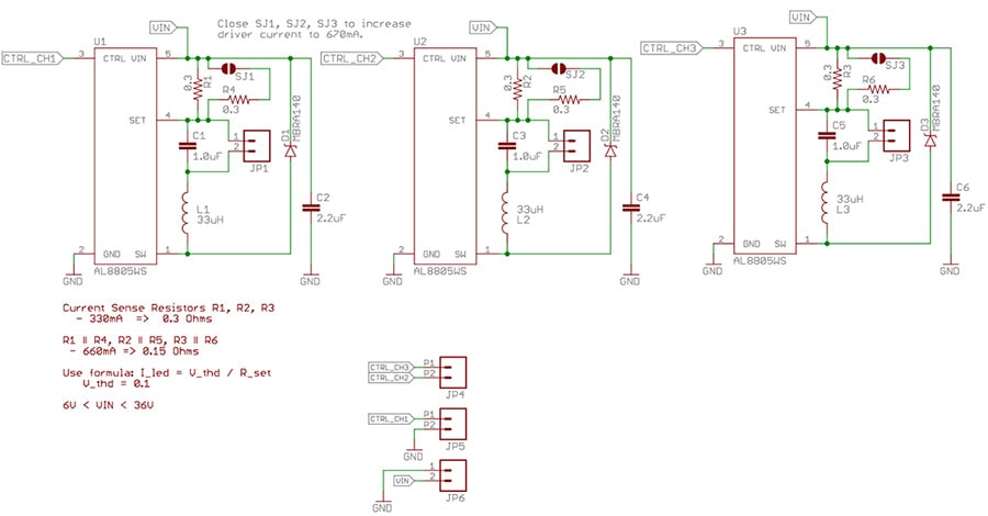
The PicoBuck LED Driver is an economical and easy to use driver that will allow you to control and blend three different LEDs on three different channels. By default, each channel is driven at 330mA; that current can be reduced by either presenting an analog voltage or a PWM signal to the board. Version 1.2 of the board adds a solderable jumper that can be closed to increase the maximum current to 660mA. The new voltage regulator also increased the voltage rating on the various components on the board, allowing it to be used up to the full 36V rating of the AL8805 part.
Three signal inputs are provided for dimming control. You can use the PWM signal from an Arduino or your favorite microcontroller to dim each channel individually, or you can tie them all to the same PWM for simultaneous dimming. Dimming can be done by an analog voltage (20%-100% of max current by varying voltage from .5V-2.5V) or by PWM (so long as PWM minimum voltage is less than .4V and maximum voltage is more than 2.4V) for a full 0-100% range. A small jumper is provided for each channel to allow you to increase the drive strength from 330mA to 660mA.
Two mounting holes for 4-40 or M3 screws are provided on either side of the PicoBuck LED Driver. The PCBs are perforated so they can be easily snapped off with a pair of pliers if a smaller footprint is desired.
Picobuck LED Driver Schematic:
Getting Started with the Picobuck LED Driver:
You'll want to get yourself some suitable LEDs,
an Arduino, and a suitable PSU. Oh and don't forget about wiring and soldering stuffs!
Ensuring that each channel is independently connected to the + and - connections of the LED it is to drive! Do not connect the + or - connections of any two channels together.
Connect like so: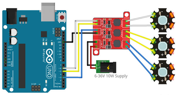
Multiple LEDs can be connected in series, as shown below, making sure the supply voltage is at least 2-3V higher than the sum of the forward voltages of the LEDs.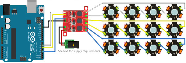
As an example, our blue 3W LEDs have a forward voltage of 3.2V to 3.8V. To be on the safe side, use the highest voltage in the range. If you want to connect four of them, you'll need a power supply of ~17V or greater (3.8V + 3.8V + 3.8V + 3.8V = 15.2V; add 2V to be on the safe side).
Example Arduino Code for the Picobuck LED Driver:
[code language="arduino"]
const int CHL_1 = 3;
const int CHL_2 = 5;
const int CHL_3 = 6;
void setup()
{
pinMode(CHL_1, OUTPUT);
pinMode(CHL_2, OUTPUT);
pinMode(CHL_3, OUTPUT);
}
void loop()
{
// Let's just step through a couple of values, so we can see how they look.
// Remember, LEDs are non-linear, so doubling the PWM output value won't
// necessarily double the apparent brightness.
analogWrite(CHL_1, 0);
analogWrite(CHL_2, 0);
analogWrite(CHL_3, 0);
delay(1000);
analogWrite(CHL_1, 64);
analogWrite(CHL_2, 64);
analogWrite(CHL_3, 64);
delay(1000);
analogWrite(CHL_1, 255);
analogWrite(CHL_2, 255);
analogWrite(CHL_3, 255);
delay(1000);
}
[/code]
Documents:
- AL8805_Datasheet (HIGH-EFFICIENCY 36V 1A BUCK LED DRIVER)
Notes:
- If you’re going to use screw terminals, this board uses two different sizes. Check the related products for both sizes you’ll need.
- It's important to note that the PicoBuck is designed for lighting either single LEDs or LEDs in series. Most LED strips are designed to be fed by a constant voltage and should not be used with the PicoBuck.
- The PicoBuck LED Driver was made in collaboration with Ethan Zonca. A portion of each sale is given back to him.
Videos
View AllClose
Related Products
")
")
LED Green - 3W Aluminum Backed PCB (Pack of 5)
Sparkfun


FemtoBuck LED Driver (COM-13716)
Sparkfun
 SparkFun COM-13104")
 SparkFun COM-13104")
LED - 3W Aluminum PCB (5 Pack, Warm White) SparkFun COM-13104
Sparkfun
 main")
")
SparkFun COM-13105 LED - 3W Aluminum PCB (5 Pack, Cool White)
Sparkfun
 1")
 2")
SparkFun COM-13107 LED - 3W Aluminum PCB (5 Pack, Blue)
Sparkfun