Description
Proto-Pic PPSERPWM2 Serial Controlled 2 Channel PWM Driver (ATTINY85)
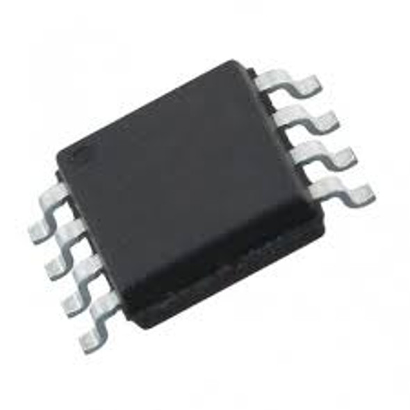
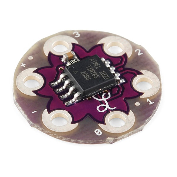
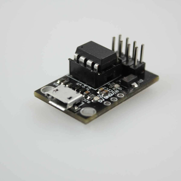
This ATTINY85 micro controller chip has been programed with our custom designed firmware to take a serial connection at 9600, and output two PWM signals, and two Enable/Direction Setting on other pins. The chip can be connected up to drive a motor using many of the available motor driver chips, for example the SN754410 Series of 1Amp, 4.5V - 36V Drivers. Designed to run at 5V, this chip is ideal for adding motor control to your microcontroller projects, and brings down the number of pins required to run almost any number of motors to 1, plus a ground connection. The chip can be programmed with an address, with a maximum if 127 devices on the serial line. Each chip is capable of driving 2 channels of PWM with 255 different levels, and 2 channels of direction either HIGH or LOW.
This chip gives you two PWM Channels and 2 logic level channels, and is ideal for driving motor driver boards. The serial protocol is easy to follow and as each chip can be addressed, you can drive more than one chip from your serial device.
This chip is designed to run at 5V, but can run on a supply voltage between 3.3V and 5.5V. Its output voltage will be the same as its input voltage. The chip should be connected up as shown below:
The protocol is 4 Bytes for regular use, there are special codes to set the address of the chip.
Connect your device at 9600 BAUD (8-N-1):
| Byte | Action |
| 255 (0xFF) | Reset the address to 1 |
| 254 (0xFE) X Y | Set address on chip X to address Y (E.g. FE 01 02 would set chip at address 1 to address 2) |
If an address higher than 127 is used it is ignored and no change will be made.
253 (0xFD) A X (A = Address) if X = 1 then PWM Freq. = 126Hz
if X is not 1 then PWM Freq. = 254Hz
To set the Direction Pin & PWM Values use: 128 (0x80) – Address – Channel – Direction - PWM
Address: Current address of the chip to access
Channel: Channel 1 or 2, you can use 3 to apply the settings to both channels
Direction: 0 or 1 (This will be the value on the direction pin)
PWM: The required PWM value 0 – 255
NOTES:
- Do not connect or disconnect devices from this chip while the power is connected, this may harm the device or the driver chip.
- It is recommended to have a capacitor across the power supply, close to the chip, to help with any Interference from connected devices.
- In SOME configurations you may have to connect pin 1 to VCC with a resistor (4.7K – 10K)
EXAMPLE USE WITH SN754410 DRIVER CHIP
The SN754410 would require a supply for the motors & we have not shown the GND connections on pins 4,5,12 & 13


