Pololu
Step-Down Voltage Regulator 6V, 2.5A - D24V25F6

- SKU:
- PPPOL2852


Description
Step-Down Voltage Regulator 6V, 2.5A - Pololu 2852
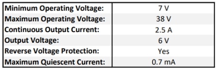
The D24V25Fx family of step-down voltage regulators generates lower output voltages from input voltages as high as 38 V. They are switching regulators (also called switched-mode power supplies (SMPS) or DC-to-DC converters) with typical efficiencies between 85% and 95%, which is much more efficient than linear voltage regulators, especially when the difference between the input and output voltage is large. The available output current is a function of the input voltage and efficiency (see the Typical Efficiency and Output Current section below), but the output current can typically be as high as 2.5 A.
At light loads, the switching frequency automatically changes to maintain high efficiencies. These regulators have a typical quiescent (no load) current draw of less than 1 mA, and the ENABLE pin can be used to put the boards in a low-power state that reduces the quiescent current to approximately 10 µA to 20 µA per volt on VIN.
The modules have built-in reverse-voltage protection, short-circuit protection, a thermal shutdown feature that helps prevent damage from overheating, and a soft-start feature that reduces inrush current.
Regulator Features:
- Input voltage:
- 4.5 V to 38 V for the version that outputs 3.3 V
- [output voltage + dropout voltage] to 38 V for output voltages of 5 V and higher (see below for more information on dropout voltage)
- Fixed 3.3 V, 5 V, 6 V, 7.5 V, or 9 V output (depending on regulator version) with 4% accuracy
- Typical maximum continuous output current: 2.5 A
- Integrated reverse-voltage protection, over-current protection, over-temperature shutoff, and soft-start
- Typical efficiency of 85% to 95%, depending on input voltage and load; the switching frequency automatically changes at light loads to maintain high efficiencies
- Typical no-load quiescent current under 1 mA; can be reduced to 10 µA to 20 µA per volt on VIN by disabling the board
- Two 0.086″ mounting holes for #2 or M2 screws
General Specifications:
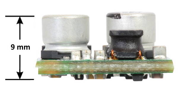
Regulator Dimensions:
- Size: 17.8 mm x 17.8mm x 9 mm (0.7" x 0.7" x 0.35")*
- Weight: 2.6 g*
* without included optional headers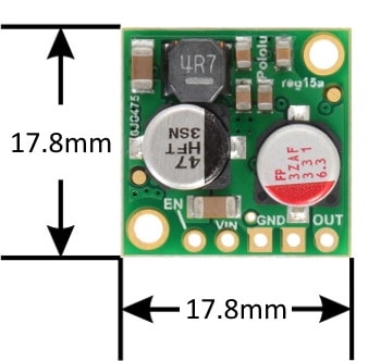
Note: see the documents section at the bottom of the page for the engineering drawing with more information on dimensions.
Using The Regulator
Connections:
This buck regulator has five connection points for four different connections: enable (EN), input voltage (VIN), 2x ground (GND), and output voltage (VOUT) as shown below: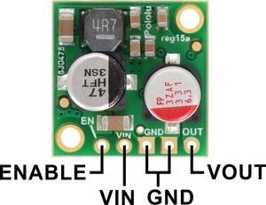
The input voltage, VIN, powers the regulator. Voltages between 4.5 V and 38 V can be applied to VIN, but for versions of the regulator that have an output voltage higher than 4.5 V, the effective lower limit of VIN is VOUT plus the regulator’s dropout voltage, which varies approximately linearly with the load (see below for graphs of dropout voltages as a function of the load).
The output voltage, VOUT, is fixed and depends on the regulator version: the D24V25F3 version outputs 3.3 V, the D24V25F5 version outputs 5 V, the D24V25F6 version outputs 6 V, the D24V25F7 version outputs 7.5 V, and the D24V5F9 version outputs 9 V.
The regulator is enabled by default: a 100 kΩ pull-up resistor on the board connects the ENABLE pin to reverse-protected VIN. The ENABLE pin can be driven low (under 0.6 V) to put the board into a low-power state. The quiescent current draw in this sleep mode is dominated by the current in the pull-up resistor from ENABLE to VIN and by the reverse-voltage protection circuit, which will draw between 10 µA and 20 µA per volt on VIN when ENABLE is held low. If you do not need this feature, you should leave the ENABLE pin disconnected.
The five connection points are labeled on the top of the PCB and are arranged with a 0.1″ spacing for compatibility with solderless breadboards, connectors, and other prototyping arrangements that use a 0.1″ grid. Either the included 5×1 straight male header strip or the 5×1 right-angle male header strip can be soldered into these holes. For the most compact installation, you can solder wires directly to the board.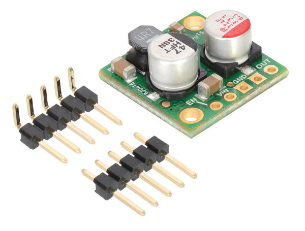
The board has two 2.18 mm (0.086″) mounting holes intended for #2 or M2 screws. The mounting holes are at opposite corners of the board and are separated by 13.5 mm (0.53″) both horizontally and vertically.
Typical Efficiency and Output Current:
The efficiency of a voltage regulator, defined as (Power out)/(Power in), is an important measure of its performance, especially when battery life or heat are concerns. This family of switching regulators typically has an efficiency of 85% to 95%, though the actual efficiency in a given system depends on input voltage, output voltage, and output current. See the efficiency graph below for more details: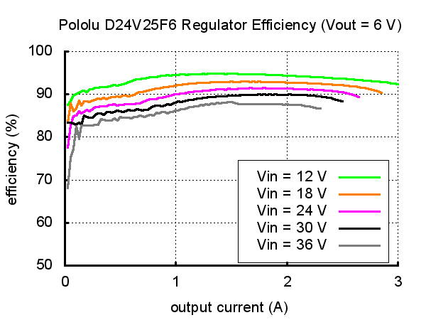
The maximum achievable output current is typically around 2.5 A, but this depends on many factors, including the ambient temperature, airflow, heat sinking, and the input and output voltage.
Typical Dropout Voltage:
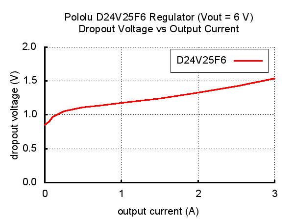
The dropout voltage of a step-down regulator is the minimum amount by which the input voltage must exceed the regulator’s target output voltage in order to ensure the target output can be achieved. For example, if a 5 V regulator has a 1 V dropout voltage, the input must be at least 6 V to ensure the output is the full 5 V. Generally speaking, the dropout voltage increases as the output current increases. See the graph below for more information on the dropout voltage for this specific regulator version.
Switching Frequency and Behaviour Under Light Loads:
The regulator generally operates at a switching frequency of around 600 kHz, but the frequency drops when encountering a light load to improve efficiency. This could make it harder to filter out noise on the output caused by switching.
Usage Warning:
- During normal operation, this product can get hot enough to burn you! Take care when handling this product or other components connected to it.
The over-current limit of the regulator operates on a combination of current and temperature: the current threshold decreases as the regulator temperature goes up. However, there might be some operating points at low input voltages and high output currents (well over 2.5 A) where the current is just under the limit and the regulator might not shut off before damage occurs. If you are using this regulator in an application where the input voltage is near the lower limit and the load could exceed 3.5A for sustained periods (more than five seconds), consider using additional protective components such as fuses or circuit breakers.
Documents:
Related Products


5V, 2.5A Step-Down Voltage Regulator D24V22F5
Pololu


Adjustable Step-Up/Step-Down Voltage Regulator S7V8A
Pololu


5V Step-Up/Step-Down Voltage Regulator S7V7F5
Pololu


Step-Down Voltage Regulator 5V, 1A - D24V10F5
Pololu


5V, 9A Step-Down Voltage Regulator D24V90F5
Pololu