


Description
5V, 2.5A Step-Down Voltage Regulator D24V22F5 - Pololu 2858
The Pololu Step-Down Voltage Regulator D24V22F5 generates a fixed output of 5V with input voltages of up to 32V. They are synchronous switching regulators (also called switched-mode power supplies (SMPS) or DC-to-DC converters) with typical efficiencies of 85% to 95%, which is much more efficient than linear voltage regulators, especially when the difference between the input and output voltage is large. These regulators can typically support continuous output currents between 1.4 A and 2.6 A, though the actual available output current is a function of the input voltage and efficiency. In general, the available output current is a little higher for the lower-voltage versions than it is for the higher-voltage versions, and it decreases as the input voltage increases.
These regulators have a typical quiescent (no load) current draw of around 1 mA, and an enable pin can be used to put the boards in a low-power state that reduces the quiescent current to approximately 5 µA to 10 µA per volt on VIN.
The modules have built-in reverse-voltage protection, short-circuit protection, a thermal shutdown feature that helps prevent damage from overheating, and a soft-start feature that reduces inrush current.
For higher-power alternatives, please consider our D36V28Fx family of step down regulators that can handle current between 2 A and 4 A and take input voltages up to 50 V.
Voltage Regulator D24V22F5 Features:
- Input voltage 4 V to 36 V
- Fixed 5 V with 4% accuracy
- Typical maximum continuous output currents between 1.4 A abd 2.6 A
- Typical efficiency of 85% to 95%, depending on input voltage, output voltage, and load
- Switching frequency: ~400 kHz
- Integrated reverse-voltage protection, over-current and short-circuit protection, over-temperature shutoff, and soft-start
- 1 mA typical no-load quiescent current; this can be reduced to approximately 5 µA to 10 µA per volt on VIN by disabling the board
- “Power good” output indicates when the regulator cannot adequately maintain the output voltage
- Two 0.086″ mounting holes for #2 or M2 screws
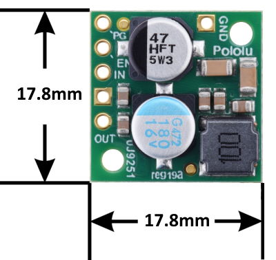
Voltage Regulator D24V22F5 Dimensions:
- Size: 17.8 x 17.8 x 8mm (0.7" x 0.7" x 0.31")
- Weight: 2.3 g
Using the Voltage Regulator D24V22F5
These buck regulators have five main connection points for five different electrical nodes: power good (PG), enable (EN), input voltage (VIN), ground (GND), and output voltage (VOUT). The board also features a second ground connection point off the main row of connections that might be convenient for applications where you are soldering wires directly to the board rather than using it in a breadboard.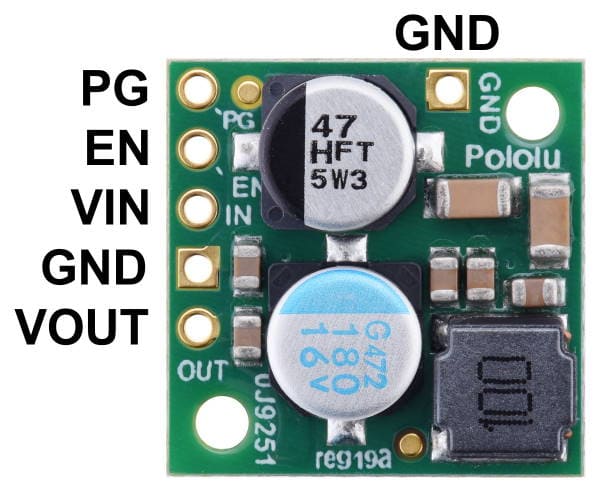
The regulator is enabled by default: a 270 kΩ pull-up resistor on the board connects the EN pin to reverse-protected VIN. The EN pin can be driven low (under 1 V) to put the board into a low-power state. The quiescent current draw in this sleep mode is dominated by the current in the pull-up resistor from EN to VIN and by the reverse-voltage protection circuit, which altogether will draw between 5 µA and 10 µA per volt on VIN when EN is held low. If you do not need this feature, you should leave the EN pin disconnected.
The “power good” indicator, PG, is an open-drain output that goes low when the regulator’s output voltage falls below around 85% of the nominal voltage and becomes high-impedance when the output voltage rises above around 90%. An external pull-up resistor is required to use this pin.
The five main connection points are labeled on the top of the PCB and are arranged with a 0.1″ spacing for compatibility with solderless breadboards, connectors, and other prototyping arrangements that use a 0.1″ grid. Either the included 5×1 straight male header strip or the 5×1 right angle male header strip can be soldered into these holes. For the most compact installation, you can solder wires directly to the board.
The board has two 0.086″ (2.18 mm) diameter mounting holes intended for #2 or M2 screws. The mounting holes are at opposite corners of the board and are separated by 0.52″ (13.21 mm) both horizontally and vertically.
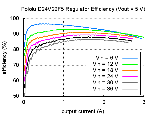
Voltage Regulator D24V22F5 Typical efficiency
The efficiency of a voltage regulator, defined as (Power out)/(Power in), is an important measure of its performance, especially when battery life or heat are concerns. This switching regulator typically has an efficiency of 85% to 95%, though the actual efficiency in a given system depends on input voltage, output voltage, and output current. See the efficiency graph below for more information.
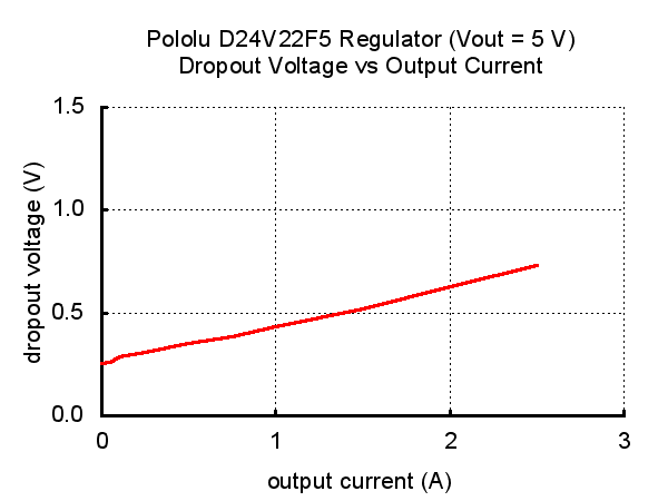
The dropout voltage of a step-down regulator is the minimum amount by which the input voltage must exceed the regulator’s target output voltage in order to ensure the target output can be achieved. For example, if a 5 V regulator has a 1 V dropout voltage, the input must be at least 6 V to ensure the output is the full 5 V. Generally speaking, the dropout voltage increases as the output current increases.Typical Dropout Voltage
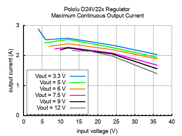
The maximum achievable output current of these regulators varies with the input voltage but also depends on other factors, including the ambient temperature, air flow, and heat sinking. The graph below shows maximum output currents that these regulators can deliver continuously at room temperature in still air and without additional heat sinking.Maximum Continuous Output Current
Warning: during normal operation, this product can get hot enough to burn you. Take care when handling this product or other components connected to it. (More generally, rewiring anything while it is powered is asking for trouble.)Four, six, and eight-wire stepper motors can be driven by the TB67S2x9FTG if they are properly connected
Documents:
Related Products


Step-Down Voltage Regulator 6V, 2.5A - D24V25F6
Pololu


5V Step-Up/Step-Down Voltage Regulator S7V7F5
Pololu


5V, 300mA Step-Down Voltage Regulator D24V3F5
Pololu


Step-Down Voltage Regulator 5V, 1A - D24V10F5
Pololu


5V, 9A Step-Down Voltage Regulator D24V90F5
Pololu