Pololu
Stepper Motor Driver Carrier TB67S279FTG (1.2A/2A)

- SKU:
- PPPOL2974


Description
Stepper Motor Driver Carrier TB67S279FTG (1.2A/2A) - Pololu 2974
The Stepper Motor Driver Carrier TB67S279FTG (1.2A/2A) is a carrier board or breakout board for Toshiba’s TB67S2x9FTG family of stepper motor drivers; we therefore recommend careful reading of the corresponding driver’s datasheet before using this product. This stepper motor driver lets you control one bipolar stepper motor and is available in two different versions: the TB67S249FTG can deliver about 1.7 A per phase continuously (4.5 A peak), and the TB67S279FTG can deliver about 1.2 A per phase continuously (2 A peak).
The two versions of this stepper driver carrier look very similar, so you should consider adding your own distinguishing marks or labels if you will be working simultaneously with multiple versions. A white box is provided on the bottom silkscreen of the board to make labeling easier. This product page applies to both versions of the TB67S2x9FTG carrier.
This version uses a TB67S279FTG driver and can deliver approximately 1.2 A per phase continuously without a heat sink or forced air flow (up to 2 A peak). It can be distinguished by the marking “S279FTG” on the driver IC.
General Specifications:
| Motor driver: | TB67S279FTG |
|---|---|
| Minimum operating voltage: | 10 V |
| Maximum operating voltage: | 47 V |
| Continuous current per phase: | 1.2 A |
| Maximum current per phase: | 2 A |
| Minimum logic voltage: | 2 V1 |
| Maximum logic voltage: | 5.5 V |
| Microstep resolutions: | full, non-circular 1/2, 1/2, 1/4, 1/8, 1/16, 1/32 |
| Current limit control: | potentiometer |
| Reverse voltage protection?: | Y2 |
| Header pins soldered?: | N |
Notes:
- This is the input logic high threshold.
- Note: Reverse voltage protection only works up to 40 V.
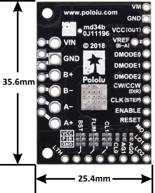
Dimensions:
- Size: 35.6 x 25.4 mm (1.0" x 1.4")
- Weight: 4.3 g
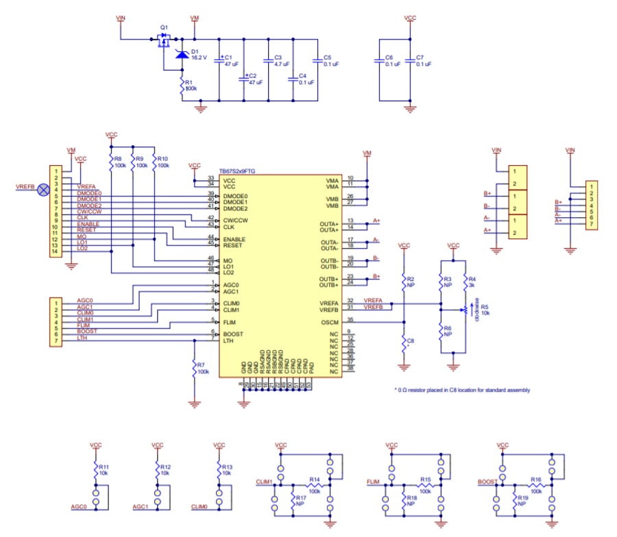
Schematic Diagram:
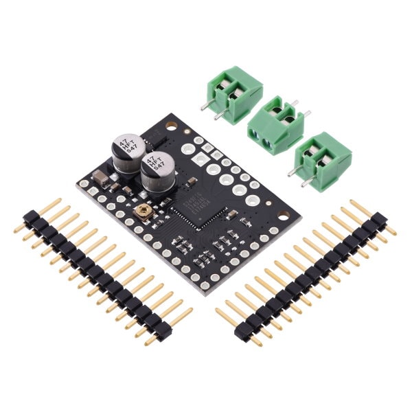
Included Hardware:
This product ships with all surface-mount components—including the TB67S2x9FTG driver IC—installed as shown in the product picture. However, soldering is required for assembly of the included through-hole parts: two 1×15-pin breakaway 0.1″ male headers and three 2-pin, 3.5 mm terminal blocks (for board power and motor outputs).
The 0.1″ male header can be broken or cut into smaller pieces as desired and soldered into the smaller through-holes. These headers are compatible with solderless breadboards, 0.1″ female connectors, and our premium and pre-crimped jumper wires. The terminal blocks can be soldered into the larger holes to allow for convenient temporary connections of unterminated power and stepper motor wires. You can also solder your motor leads and other connections directly to the board for the most compact installation.
Power Connections:
The driver requires a motor supply voltage of 10 V to 47 V to be connected across VIN and GND. This supply should be capable of delivering the expected stepper motor current.
A 5 V output from the TB67S2x9FTG’s internal regulator is made available on the VCC pin. This output can supply up to 5 mA to external loads.
Motor Connections:
Four, six, and eight-wire stepper motors can be driven by the TB67S2x9FTG if they are properly connected
Additional Information:
Follow us on Instagram for new stock alerts, promotions and inspiration for your next project! Give us a follow and talk shop with your fellow tinkerers!
Documents:
Videos
View AllClose
Related Products


Stepper Motor Driver Carrier STSPIN820
Pololu


TB67S2x9FTG Stepper Motor Driver Carriers


A4988 Stepper Motor Driver Carrier
Pololu


Stepper Motor Driver Breakout Board, TB6612, 1.2A DC (2448)
AdaFruit


Stepper Motor Driver Carrier TB67S249FTG (1.7A/4.5A)
Pololu