Description
STSPIN220 Low-Voltage Stepper Motor Driver Carrier
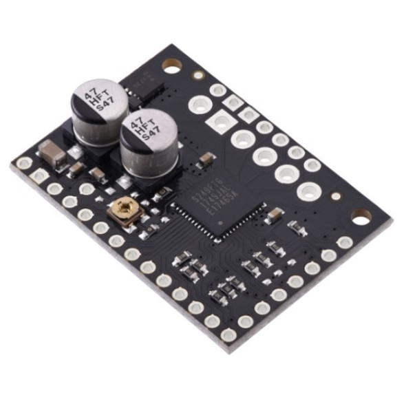
The STSPIN220 Low-Voltage Stepper Motor Driver Carrier breaks out the STSPIN220 IC onto a simple to use breakout board. Capable of microstep resolutions down to a tiny 1/256 of a step and allowing you to control a single bipolar stepper motor at a continuous 1.1A per phase. All of this without the need of a heat sink or air flow due to highly efficent power dissipation.
Low-Voltage Stepper Motor Driver Features
-
- Simple step and direction control interface
- Nine different step resolutions down to 256 microsteps: full-step, half-step, 1/4-step, 1/8-step, 1/16-step, 1/32-step, 1/64-step, 1/128-step, and 1/256-step
- Adjustable current control lets you set the maximum current output, which lets you use voltages above your stepper motor’s rated voltage to achieve higher step rates
- Motor supply voltage: 1.8 V to 10 V
- Can deliver 1.1 A per phase continuously without need for cooling
- Can interface directly with 3.3 V and 5 V systems
- Over-temperature thermal shutdown, over-current shutdown, and short circuit protection
- 4-layer, 2 oz copper PCB for improved heat dissipation
- Exposed solderable ground pad below the driver IC on the bottom of the PCB
Included Kit
-
-
- STSPIN220 Low-Voltage Stepper Motor Driver Carrier
- 1×16-pin breakaway 0.1″ male headers
-
Control inputs and status outputs
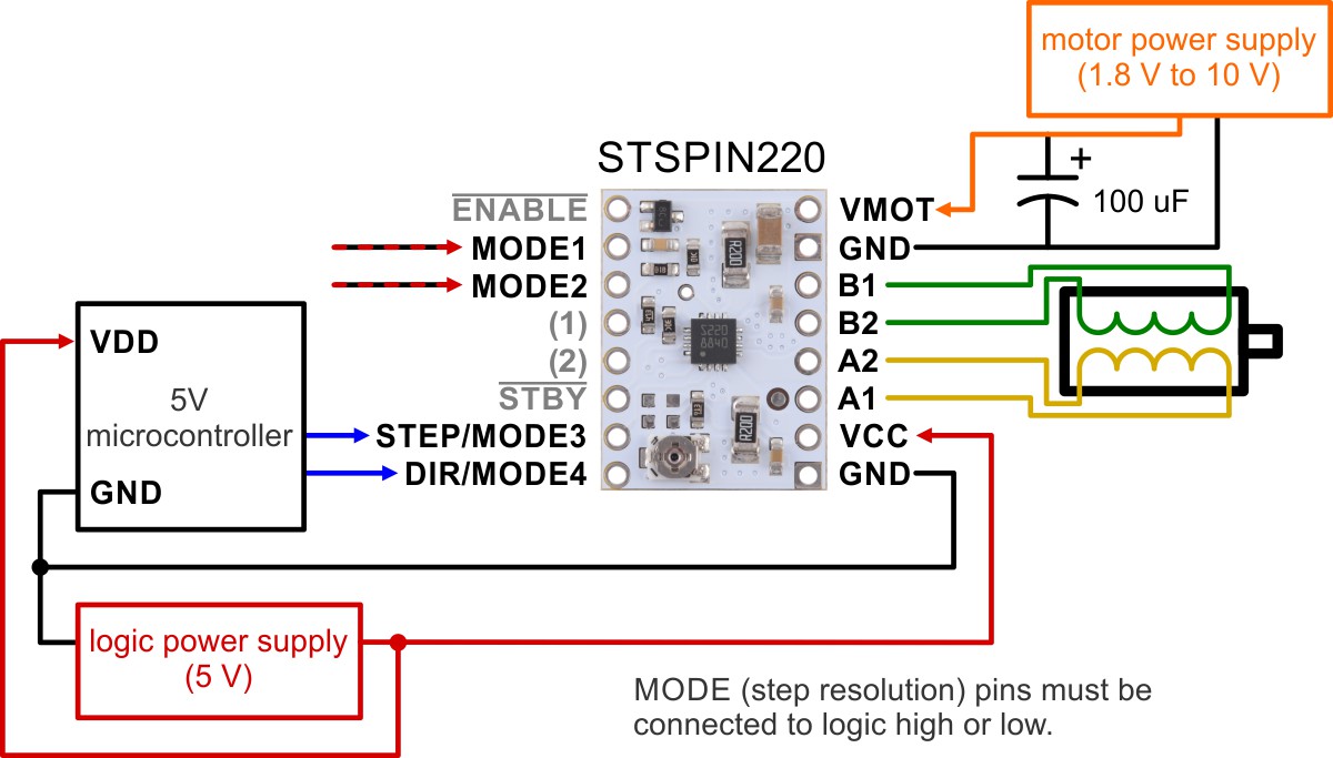
The rising edge of each pulse to the STEP (STCK) input corresponds to one microstep of the stepper motor in the direction selected by the DIR pin. Unlike most of our other stepper motor driver carriers, the STEP and DIR inputs are floating, so they must be connected to logic high or low to ensure proper operation.
The STSPIN220 IC has two different inputs for controlling its power states, STBY/RESET and EN/FAULT:
-
-
- When the STBY pin is driven low, the driver enters a low-power mode, disables the motor outputs, and resets the translation table. We call this pin STBY on our board based on the logic of how it works, but it is a direct connection to the STBY pin on the driver. The board pulls this pin high by default.
- The EN pin is inverted by our carrier board and presented as ENABLE, which makes it the same way as the enable pins on our various other stepper motor drivers with this form factor. It is pulled low on the board to enable the driver by default, and it can be driven low to disable the outputs.
-
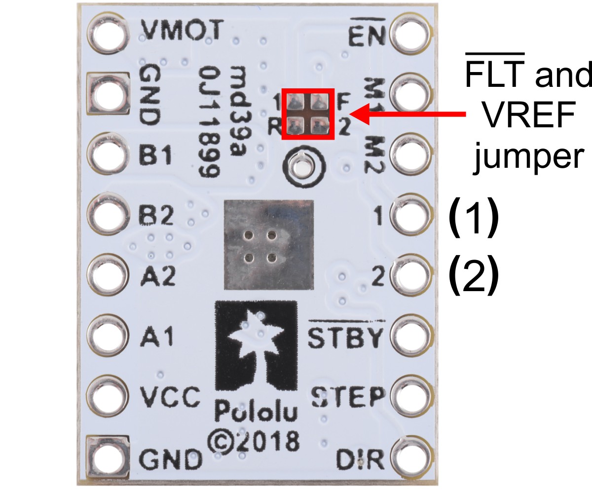
The STSPIN220 can detect several fault (error) states that it reports by driving its EN/FAULT pin low. The FAULT pin is not made available by default (to avoid conflicts when using the STSPIN220 carrier as a drop-in replacement for our other stepper motor driver carriers), but it can be connected to the pin labeled “(1)” or “(2)” by bridging the surface mount jumper labeled “F” on the bottom side of the board to the corresponding pad labeled “1” or “2”.
Low-Voltage Stepper Motor Driver Documents
-
- STSPIN220 datasheet (1MB pdf)
- Schematic diagram of the STSPIN220 Stepper Motor Driver Carrier (111k pdf)
- Dimension diagram of the STSPIN220 Stepper Motor Driver Carrier (326k pdf)
- 3D model of the STSPIN220 Stepper Motor Driver Carrier (5MB step)
- Drill guide for the STSPIN220 Stepper Motor Driver Carrier (37k dxf)
- AN4923 application note for the STSPIN220: step-mode selection and on-the-fly switching to full-step (414k pdf) The STSPIN220’s integrated sequencer can provide a resolution up to 256 microsteps, but it is always possible to switch to the full-step operation on-the-fly. This document describes how to select the step resolution and manage the switch between the microstep and full-step operation.


