Description
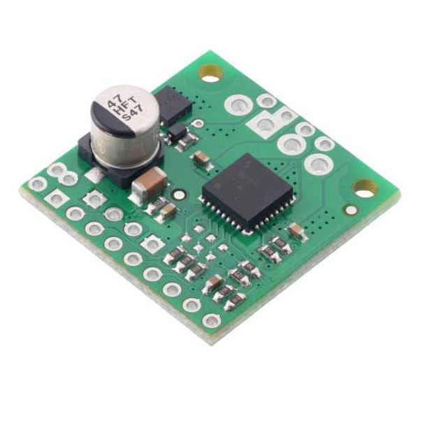
TB9051FTG Single Brushed DC Motor Driver Carrier
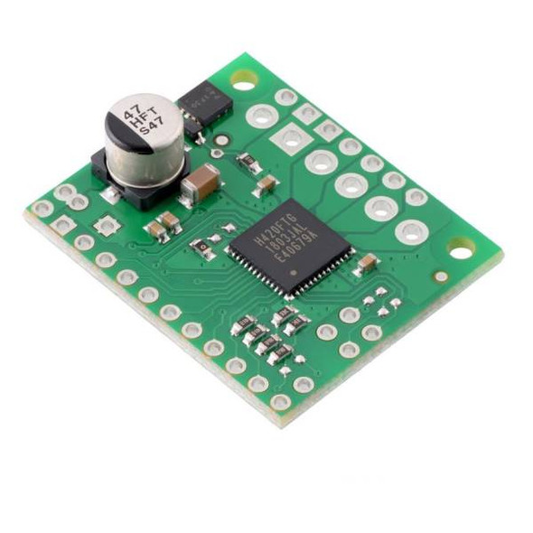
The TB9051FTG Single Brushed DC Motor Driver Carrier is a single-channel H-Bridge Motor breakout board that has the capability for bidirectional control of a DC motor from 4.5V to 28V. Supplying a continuous 2.6A, the Motor Driver can hit peak currents of up to 5A if only for a few seconds! The TB9051FTG is an excellent bit of kit however its SMD design can make it challenging for a beginner to use, this breakout board opens the IC up so you won't have that problem!
Features
- Single-channel H-bridge motor driver
- Motor supply voltage: 4.5 V to 28 V
- Output current: up to 2.6 A continuous (5 A peak)
- Automatic current chopping feature helps prevent overheating by gracefully reducing power rather than abruptly shutting down
- Under-voltage lockout and protection against over-current/short-circuit and over-temperature
- Carrier board adds reverse-voltage protection
- Active-low error output indicates over-current, over-temperature, under-voltage, or VCC over-voltage condition
- Compact size (1.0″ × 1.0″)
- Exposed solderable ground pad below the driver IC on the bottom of the PCB
Included Parts
-
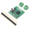
- 1× 17-pin breakaway 0.1″ male header
- 2x 2-pin, 3.5 mm terminal blocks
Motor Driver Carrier Specifications
| Motor driver: | TB9051FTG |
|---|---|
| Motor channels: | 1 |
| Minimum operating voltage: | 4.5 V |
| Maximum operating voltage: | 28 V |
| Peak output current per channel: | 5 A |
| Continuous output current: | 2.6 A |
| Current sense: | 0.5 V/A |
| Maximum PWM frequency: | 20 kHz |
| Reverse voltage protection?: | Y |
Truth Tables
| TB9051FTG simplified truth table (PWM1 + PWM2) | ||||||
|---|---|---|---|---|---|---|
| Inputs | Outputs | Operation | ||||
| EN | ENB | PWM1 | PWM2 | OUT1 | OUT2 | |
| 1 | 0 | PWM | 0 | PWM (H/L) | L | forward/brake at speed PWM % |
| 0 | PWM | L | PWM (H/L) | reverse/brake at speed PWM % | ||
| 0 | 0 | L | L | brake low (outputs shorted to ground) | ||
| 1 | 1 | L | L | |||
| 0 | X | X | X | Z | Z | coast (outputs floating/disconnected) |
| X | 1 | X | X | Z | Z | |
| TB9051FTG simplified truth table (PWM1 + PWM2 + EN) | ||||||
|---|---|---|---|---|---|---|
| Inputs | Outputs | Operation | ||||
| EN | ENB | PWM1 | PWM2 | OUT1 | OUT2 | |
| PWM | 0 | 1 | 0 | PWM (H/Z) | PWM (L/Z) | forward/coast at speed PWM % |
| 0 | 1 | PWM (L/Z) | PWM (H/Z) | reverse/coast at speed PWM % | ||
| 0 | X | X | X | Z | Z | coast (outputs floating/disconnected) |
| X | 1 | X | X | Z | Z | |
Pinout
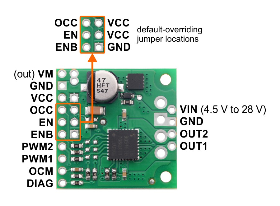
| PIN | Default State | Description |
|---|---|---|
| VIN | Reverse-protected 4.5 V to 28 V board power supply input. | |
| GND | Ground connection points for the motor and logic supplies. The control source and the motor driver must share a common ground. | |
| VM | These pins give access to the motor power supply after the reverse-voltage protection MOSFET (see the board schematic below). They can be used to supply reverse-protected power to other components in the system. VM is generally intended as an output, but it can also be used to supply board power, and some of the VM and GND holes are spaced for the addition of an optional through-hole capacitor. | |
| OUT1 | Motor output 1. | |
| OUT2 | Motor output 2. | |
| VCC | 5 V logic supply input. | |
| OCC | LOW | Over-current response configuration input: by default, the driver remains disabled after an over-current condition, but if OCC is high, it automatically tries to resume driving after a short delay instead. |
| EN | LOW | Enable input: when EN is low, OUT1 and OUT2 are set to high impedance. PWM can be applied to this pin (typically done with ENB low and either PWM1 or PWM2 high). The default is for both enable pins to be disabling the driver. |
| ENB | HIGH | Inverted enable input: when ENB is high, OUT1 and OUT2 are set to high impedance. Inverted PWM can be applied to this pin (typically done with EN high and either PWM1 or PWM2 high). The default is for both enable pins to be disabling the driver. |
| PWM1 | LOW | Control/PWM input for OUT1. |
| PWM2 | LOW | Control/PWM input for OUT2. |
| OCM | Current monitor output: this pin provides an analog current-sense feedback voltage of approximately 500 mV per amp (only active while H-bridge is driving) through an on-board RC filter. | |
| DIAG | HIGH | Diagnostic error output: driven low when certain faults have occurred or when the driver is disabled by the EN or ENB inputs. Otherwise, the board pulls this pin up to VCC. |
Motor Driver Carrier Documents
- TB9051FTG datasheet (2MB pdf)
- Schematic diagram of the TB9051FTG Single Brushed DC Motor Driver Carrier (147k pdf)
- Dimension diagram of the TB9051FTG Single Brushed DC Motor Driver Carrier (257k pdf)
- 3D model of the TB9051FTG Single Brushed DC Motor Driver Carrier (4MB step)
- Drill guide for the TB9051FTG Single Brushed DC Motor Driver Carrier (58k dxf)

